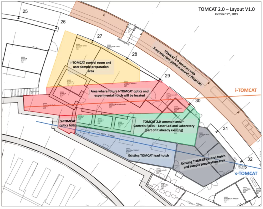
The TOMCAT 2.0 upgrade will be deployed on two beamlines: (i) I-TOMCAT, based on a superconducting, short-period undulator (SCU10) and (ii) S-TOMCAT, powered by a superconducting high-field longitudinally graded bending magnet.
I-TOMCAT will be installed adjacent to S-TOMCAT at Sector 2 of the SLS. As for any new beamline, I-TOMCAT will require a new front-end, an optical and an experimental hutch, as well as dedicated control rooms and sample preparation areas. The planned maximum beamline length will be 40 m. The proximity to S-TOMCAT will allow us to synergistically share the location of control racks, existing specialized labs, as well as mitigate shielding costs. For S-TOMCAT, we foresee the construction of a small optics hutch to host a ML-monochromator (now in the front-end) and a Bent-Laue high energy monochromator/beam-expander. Beamline repositioning following the displacements of the source point has been considered and related costs included in the budget request. Figure 2 presents the first conceptual layout of TOMCAT 2.0.
S-TOMCAT will deliver energies potentially up to 80 keV and accommodate samples up to 50 mm in diameter. I-TOMCAT will provide photons up to 45 keV (60 keV for the SCU10) for samples up to 1 mm diameter and will be optimized for high-speed TXM imaging. Some methods and end-stations will be interchangeable between S-TOMCAT and I-TOMCAT, as summarized in Table 1.
| S-TOMCAT | I-TOMCAT | |
|---|---|---|
| Source | Superbend 4T (6T) | U14 (SCU10) |
| Energy range | 10-50 keV (10-80 keV) | 8-45 keV (8-60 keV) |
| Optics | Multilayer monochromator (MLM) Bent Laue (magic condition) | Channel-cut MLM-based harmonic suppression |
| Broad-band option | White beam (filtered) | Pink beam (single harmonic) |
| Sample diameter | < 50 mm @ 25 m | < 1 mm @ 30 m |
| Techniques | WB-DCT OD-Talbot interferometry Wide-field tomography | TXM Zernike phase contrast Fourier ptychography XRF-CT |
| Detectors | 20 kpix horizontal High-NA optical coupling GigaFRoST2.0 | MOENCH(s) High-NA optical coupling GigaFRoST2.0 |
| Endstations | Generous in-situ, operando, and in-vivo capabilities Interchangeable sample holders Versatile sample manipulators | Generous in-situ, operando, and in-vivo capabilities Interchangeable sample holders Versatile sample manipulators |
For more details on the beamline sources, front ends, optics, operation modes, IT requirements and controls please have a look at the SLS 2.0 Beamline Conceptual Design Report (p. 360ff) published on January 25, 2021.

