Cristallina-Q
Proposals are due on 15.09.2025 - Cristallina-Q welcomes users with the Ultralow-T Vectormagnet experimental station. Please visit the call website and see the description below for more details.
Due to the inherent challenges with the ultralow-T environment and the connected operational limitations, proposers must contact the Cristallina-Q team well ahead of submission.
The Cristallina-Q experimental station explores uncharted territory in quantum condensed-matter research by utilising a novel variant of the “diffraction-before-destruction” concept that is widely used in serial femtosecond crystallography to outrun structural damage from impact ionisation. Taking advantage of the ultrashort sub-femtosecond hard X-ray pulses available at SwissFEL, Cristallina-Q extends this scheme to outrunning the alterations to electronic orders and imaging them in the ultralow temperature quantum limit: Diffraction patterns are recorded before the onset of beam-induced ionisation damage and heating. Heating inevitably takes place, but unless the total heat load is too large, the quantum state recovers before the arrival of the next pulse.
Cristallina-Q is realised in collaboration with the Laboratory for Quantum Matter Research of Prof. Johan Chang (UZH) and is partially funded via the SNSF R’Equip scheme.
Cristallina-Q experimental stations
Cristallina-Q operates the following experimental stations:
The experimental station is based on a customised Oxford Instruments cryogen-free Triton 3He-4He dilution refrigerator with a base temperature of just below 10 mK without additional heat load, and a cooling power of ~400 µW at 100 mK, ~2 mW at 200 mK and ~7 mW and 500 mK.

The lowest achievable sample temperature in an experiment is directly linked to the FEL repetition rate and beamline transmission. The instrument is predominantly used together with the "pink beam" sub-femtosecond mode, or the monochromatic short pulse mode, see the beam parameter overview below. Photon flux and thus the average beam heating is similar in both modes of operation. The expected temperatures for unattenuated beam are about 1 K at 100 Hz, 0.7 K at 25 Hz and 0.4 K at 5 Hz. Temperatures below 0.2 K can be reached at 1 Hz operation and 20% transmission, while sub-100 mK has been demonstrated at 1 Hz and 1% transmission. These performance estimates are however strongly dependent on the type of sample and the experimental setup, e.g. the quality of sample thermalisation and the beam size.
Sample conditions can be tuned with the superconducting split-coil vector magnet achieving a maximum of 5.2 T vertical and 0.6 T horizontal field. The operation limits can be summarised by two modes:
- Vertical field mode: Vertical magnetic field up to 5.2 T with a possible addition of a horizontal component up to 0.23 T, corresponding to 2.5° tilt of the magnetic field vector at 5.2 T towards the horizontal plane in any direction.
- Isotropic field mode: Magnetic field vector in any direction with a strength up to 0.6 T.
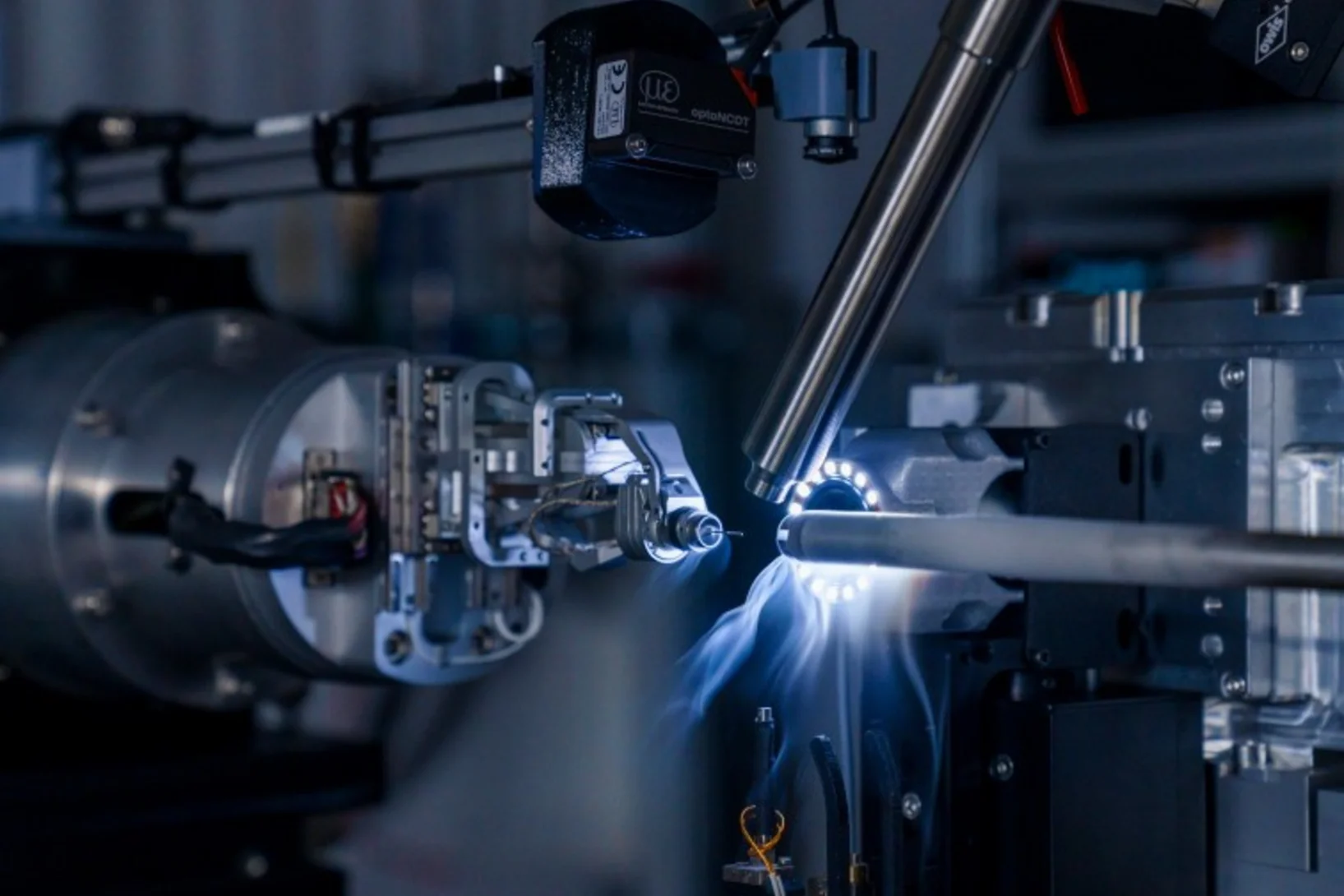
The four ±55° horizontal openings are designed so that any combination of θ and 2θ angles can be accessed within the horizontal scattering plane by thoughtful sample holder design and rotational positioning of cryostat-sample. Vertical scattering of ±10° is also possible. The magnet viewing angles are matched with a series of windows: To reach the sample, the beam passes through a 500-µm thick, high-purity beryllium vacuum window and, temporarily, two 130-µm thick mylar windows with a thin sputtered aluminium layer to minimise infrared radiation transmission. The same applies for the scattered beam path to the detector.
Due to the stiff pulse tube compressor leads, the range of cryostat rotation along the vertical axis (θ) is currently limited to ±20° from a selected θ angle.
Samples are loaded at room temperature into a versatile sample puck platform as shown below. It mates with a docking connector below the mixing chamber plate with a good thermal contact and reliable electrical connection. The docking interface features electrical connectors for a total of 48 twisted-pair DC leads (normal and/or superconducting), as well as 10 coaxial lines for higher frequency signals. No sample puck exchange can be performed during the beamtime, thus multiple samples on one sample holder are recommended, likely resulting in a custom sample holder plate being required. Due to the long cooldown time, sample mounting has to take place at least one week before beamtime start.

This setup is currently under commissioning.
Beam parameter overview
- The beamline accepts photon energies over the full Aramis range (2 - 13 keV) in pink beam mode.
- A four-bounce Si (111) double channel-cut monochromator can be inserted to operate in monochromatic mode, maintaining the beam on the same trajectory as in pink beam mode; the monochromator accepts photon energies above 2.7 keV.
- Currently, the usage of photon energies below ~5 keV is not recommended due to higher absorption of the beamline diamond exit window. Furthermore, when operating the Ultralow-T Vectormagnet, additional absorption occurs due to unavoidable air gaps as well as to the beryllium and mylar windows of the cryostat.
- Two photon operation modes are used standard:
- Broadband sub-femtosecond: Pulse energy ~10 µJ with the natural FEL spectrum bandwidth <0.5% (cumulated).
- Monochromatic sub-10 femtosend: Pulse energy ~10 uJ after the monochromator, with bandwidth ~0.013% given by the Si(111). Optionally, the pulse length can be increased up to 30 fs for more pulse energy.
- The beam can be focused on the sample to reach beam sizes below 2 x 2 µm2. However, to minimize local heating of the sample, beam sizes of order 100 x 100 µm2 and larger are recommended. The beam size on the sample is tuned by bending the KB mirrors. When using the Ultralow-T Vectormagnet, it cannot be verified in-situ without displacing the setup, and can only be inferred from indirect measurements at two locations before and after the instrument, resulting in limited accuracy for beam sizes smaller than ~20 µm. Alternatively, the beam size at the sample position can be measured at the beginning of the beamtime at the expense of a couple of hours to move the Vectormagnet setup downstream, insert a high-resolution screen at the sample position, and then reposition the setup.
- Shot-by-shot beam intensity normalisation is available with the I0 monitor as the last beamline element after the focusing mirrors and the beam clean-up slits.
- For more details on the beamline see Cristallina beamline webpage.
General infrastructure
- For diffraction experiments, Cristallina-Q operates a Jungfrau 1.5M pixel detector. The larger Jungfrau 8M detector in operation with the Cristallina-MX experimental stations, as well as diodes for flexible general-purpose use, are available on demand.
- For larger sample-detector distances (up to 6m depending on the scattering geometry), helium-filled or vacuum flight tubes can be assembled.
- General purpose beam clean-up slits with flexible mounting are available with a maximum opening of 7 x 7 mm2.