

SwissFEL is a compact, high-brilliance, soft and hard X-ray Free Electron Laser (FEL) facility laser composed of two parallel beam lines seeded by a common linear accelerator (LINAC), and a two-bunch photo-injector. For the injector, an innovative dual-photocathode laser scheme has been developed based on state-of-the-art Ytterbium femtosecond laser systems. We just published an overview of the the SwissFEL Photo Cathode Drive Lasers (PCDL) performance, pulse shaping capabilities as well as the versatility of the systems, which allow many different modes of operation of SwissFEL [1]. The full control over the SwissFEL electron bunch properties via the unique architecture of the PCDL will enable in the future the advent of more advanced FEL modes; these modes are, but not restricted to, the generation of single or trains of sub-fs FEL pulses, multi-color FEL and finally the generation of fully coherent X-ray pulses via laser-based seeding.
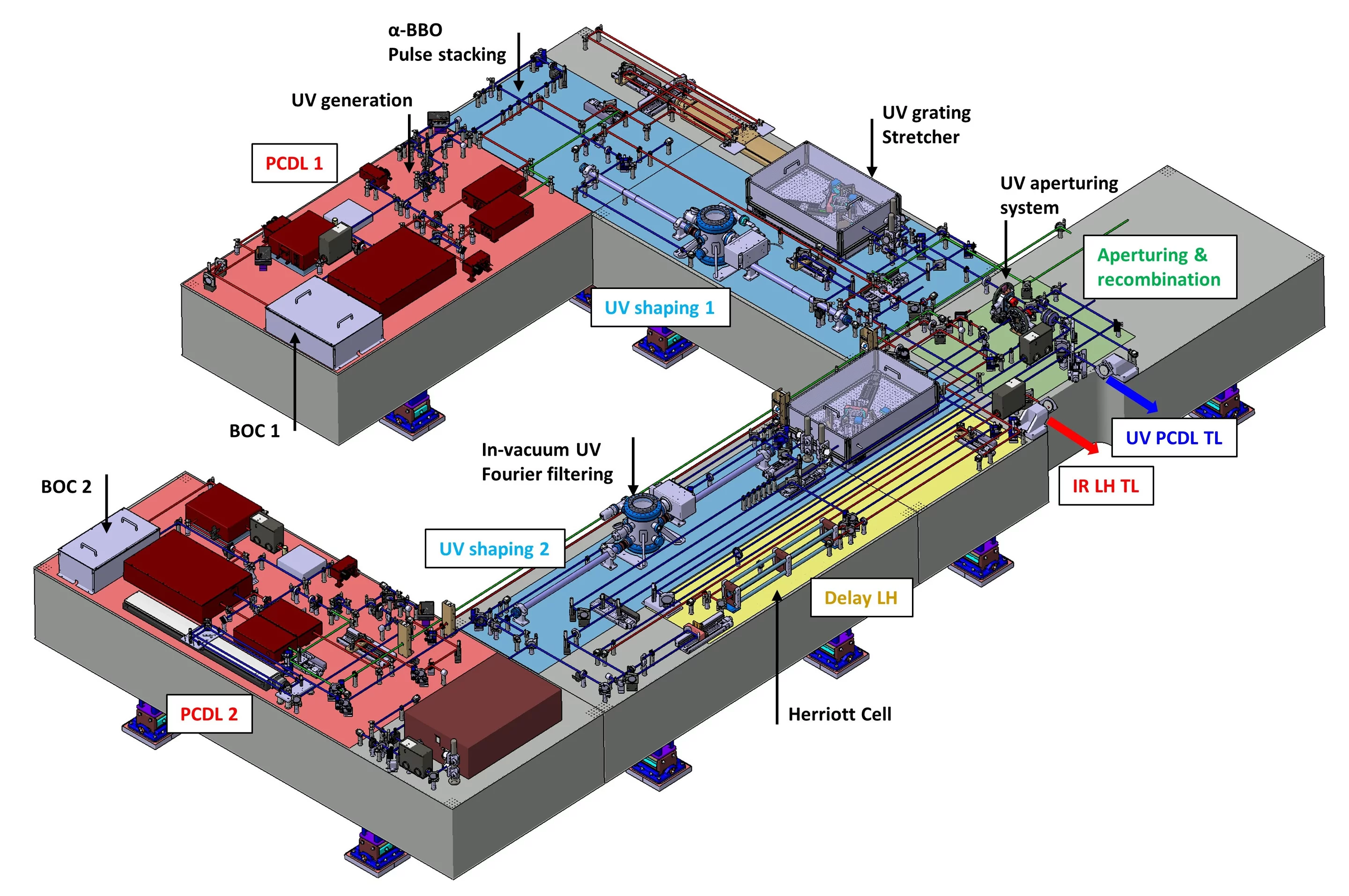
As described in the introduction, the SwissFEL photocathode drive laser must deliver two deep-UV pulses separated by 28 ns in order to seed the hard and soft X-ray lines of the FEL. The deep-UV pulse duration, energy and temporal shape must be independently adjustable for each line. The LH and short probe pulses must be available as well. These requirements are fulfilled by an accurate and precise design of the complete optical setup as shown in Figure 1.
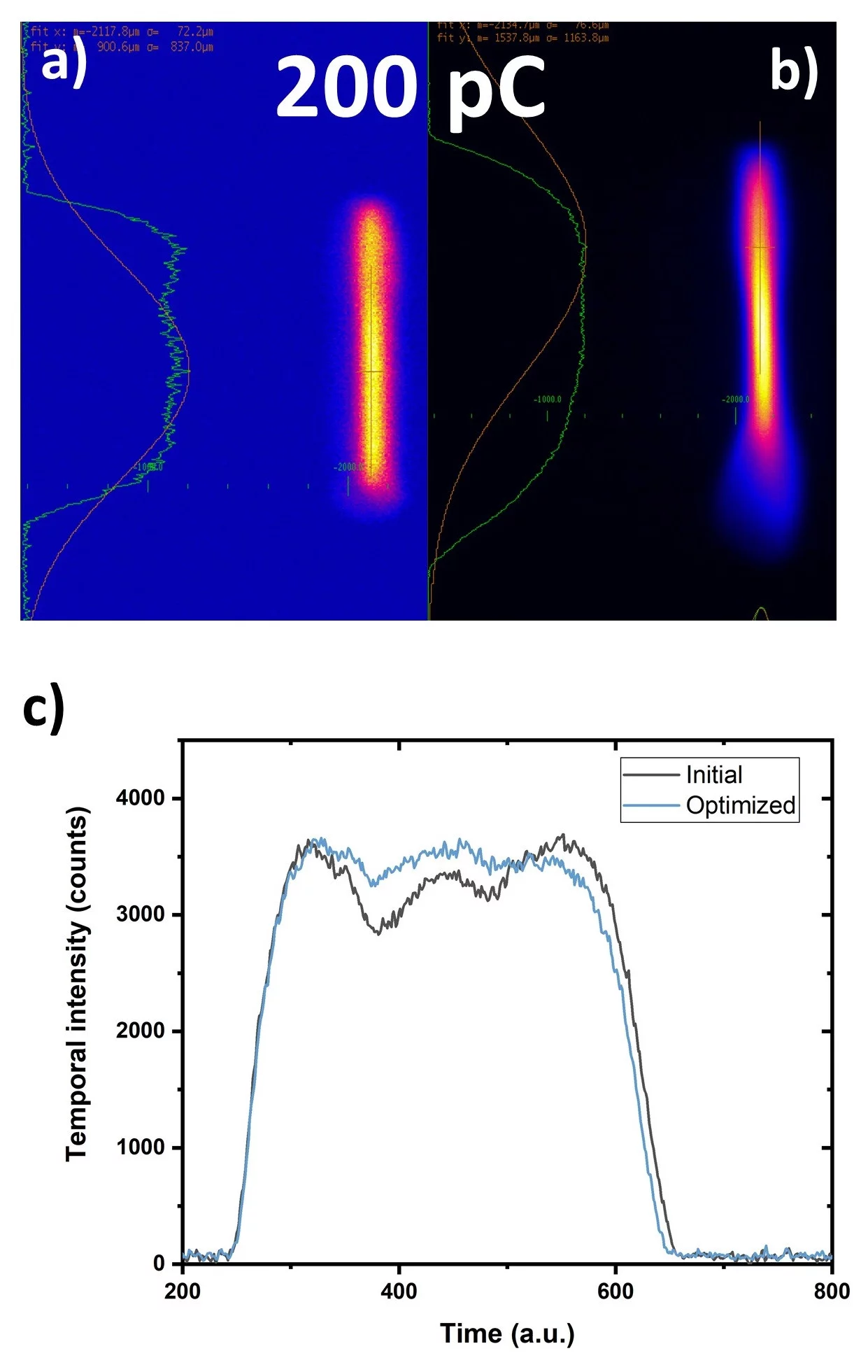
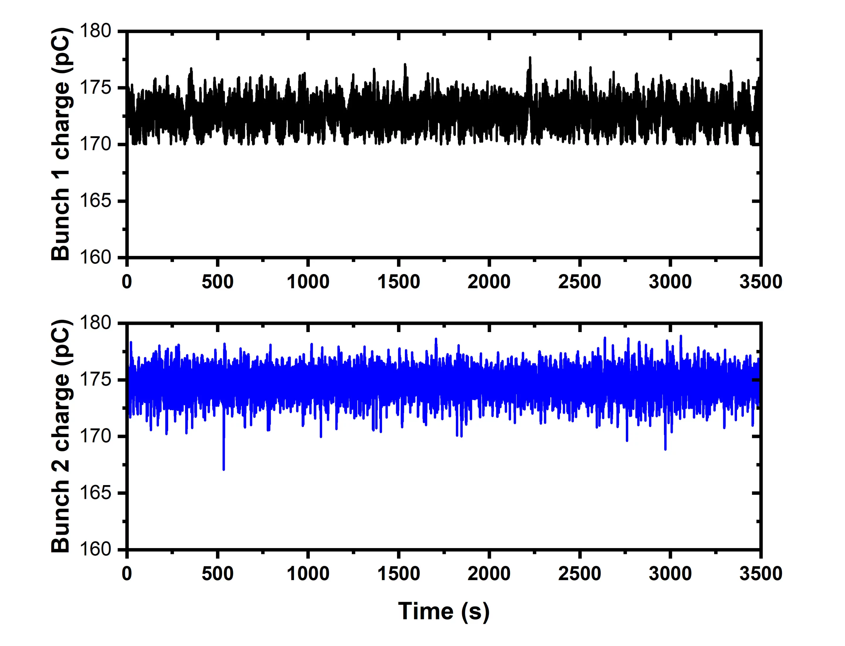
In order to produce the desired flat-top temporal profile of the electron bunch, we applied temporal shaping of the UV-PCDL in the time domain. The chosen technique consists of stacking individual replicas of orthogonally polarized pulses and is known as ‘pulse stacking’. This technique has proven to be one of the most efficient and robust with respect to the suitability for operation in large scale research facilities. Figure 2 shows the optimized flat-top electron bunch temporal profile generated by the PCDL. Figure 3 shows the charge of bunch 1 (black) and bunch 2 (blue) over 3500 seconds. The charge stability is measured to be 1.01 % and 1.04 % rms respectively.
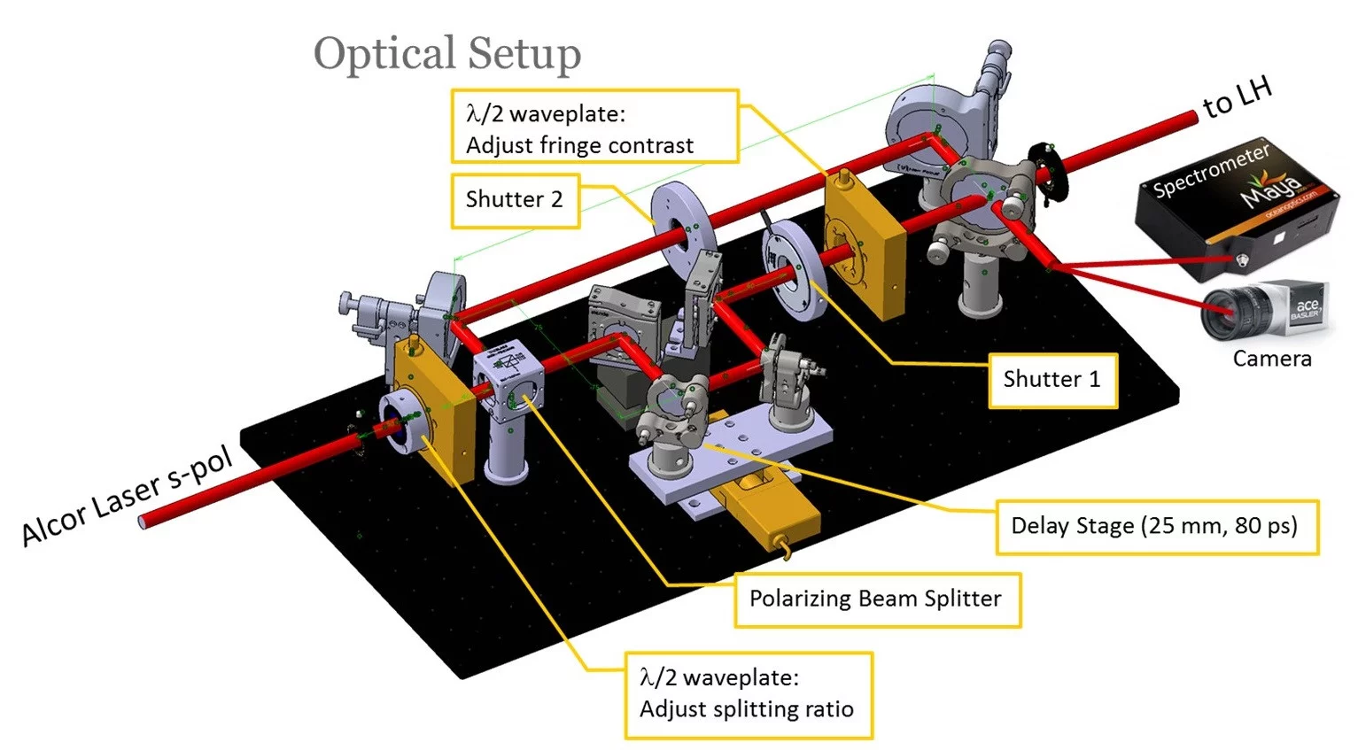
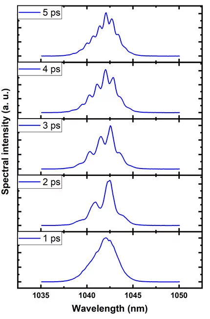
Each photocathode drive laser also delivers a so-called ‘laser heater’ (LH) output beam in addition to the main photocathode drive beam. The LH output delivers Gaussian, 50 ps duration FWHM pulses that are overlapped in space and time with the electron bunch in the LH-chicane. The primary aim of the LH is to induce a controllable increase of the uncorrelated energy spread of the electron bunch. The heating suppresses microbunching instabilities which otherwise may limit the FEL performance. Moreover, it was recently demonstrated that the use of a spectrally shaped LH laser pulse allows advanced optical control of the x-ray generation process. The manipulation of the spectro-temporal amplitude of the LH laser pulse allows control of the longitudinal energy spread of selected portions of the electron bunch. This manipulation allows the duration of the FEL photon pulse to be controlled and sliced with femtosecond precision. A controlled temporal modulation can be obtained by making use of the interference pattern of two replicas of the LH pulse. For this, a Mach-Zehnder type interferometer was constructed (Figure 4). The input chirped beam is split into two independent arms, one of them having a motorized delay line in order to set the relative delay between the two replicas before they are recombined. Figure 5 shows the typical interference pattern obtainable with the LH shaper for various delays between the two replicas. The combined, structured pulse, can be used to limit the FEL emission to isolated regions of the electron bunch where the emittance has not been spoiled by interaction with peaks in the LH intensity profile. Accurate control of the modulation period may open new opportunities such as the generation of sub-fs FEL pulses.
Further details on the PCDL architecture and capabilities are describe in reference [1].
References
[1] Bettoni, S., Cavalieri, A., Dax, A., Divall, E., Hauri, C., Hunziker, S., Huppert M., Kaiser M., Paraliev M., Sydlo C., Vicario C. and Trisorio A., Overview of SwissFEL dual-photocathode laser capabilities and perspectives for exotic FEL modes. High Power Laser Science and Engineering, 9, E51. (2021)
https://doi.org/10.1017/hpl.2021.36
[2] C. Vicario, S. Bettoni, A. Lutman, A. Dax, M. Huppert, and A.Trisorio, Two-color x-ray FEL by photocathode laser emittance spoiler, Phys. Rev. Accel. Beams 24, 060703 (2021).
Contact
Dr. Alexandre Trisorio
Gun Laser Group
+41 56 310 5302
alexandre.trisorio@psi.ch