General Layout
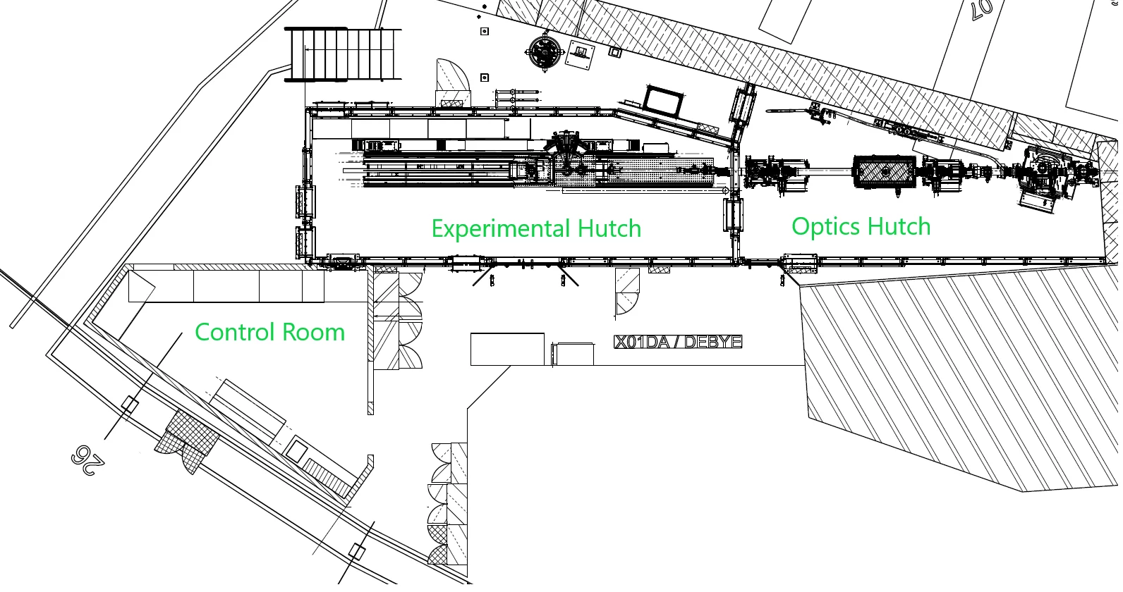
An overview of the beamline hutches is given below. The superbending magnet photon source and the front-end are to the right, inside the machine tunnel and not given on the figure. A chemistry lab intended for sample-preparation and machine lab will be situated opposite of the experimental hutch with an in between working space area for experimental setup installation. The control hutch will be situated adjoining the experimental hutch with an installed chicane for pass through of device communication cables for remote control.
Source
The following table shows the main properties of the X-ray source for Debye after the SLS Upgrade.
| Ring energy | eE | 2.7 | GeV |
|---|---|---|---|
| Ring current | eI | 400 | mA |
| Magnetic field | B | 3.5 - 5 | T |
| Critical Energy | Ec | 17.0 - 24.2 | keV |
| Electron beam size | σX | 7.2 | µm |
| Electron beam size | σY | 6.8 | µm |
| Electron beam emittance | εX | 0.157 | nm rad |
| Electron beam emittance | εY | 0.01 | nm rad |
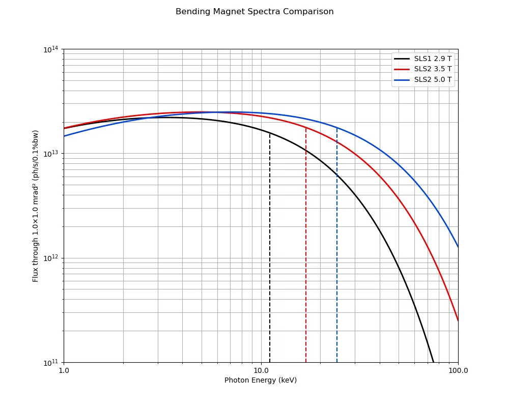
Flux curves of the superbending magnets are shown in the image below. The current superbending magnet with 2.1 T will be replaced during the SLS Upgrade to a superbending magnet with a variable field strength of 3.5 T or 5 T (changeable during machine shutdowns).
Optics
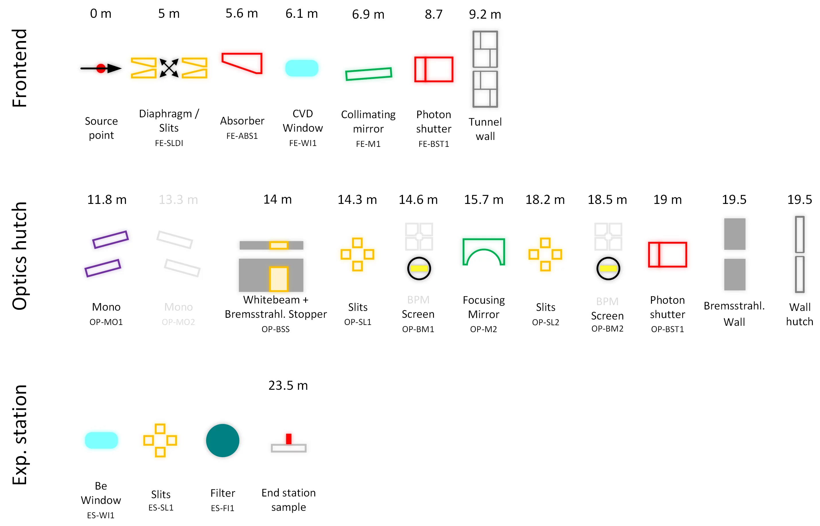
The planned optical scheme for the Debye beamline, their functions and position from the source are given here.
X-ray mirrors
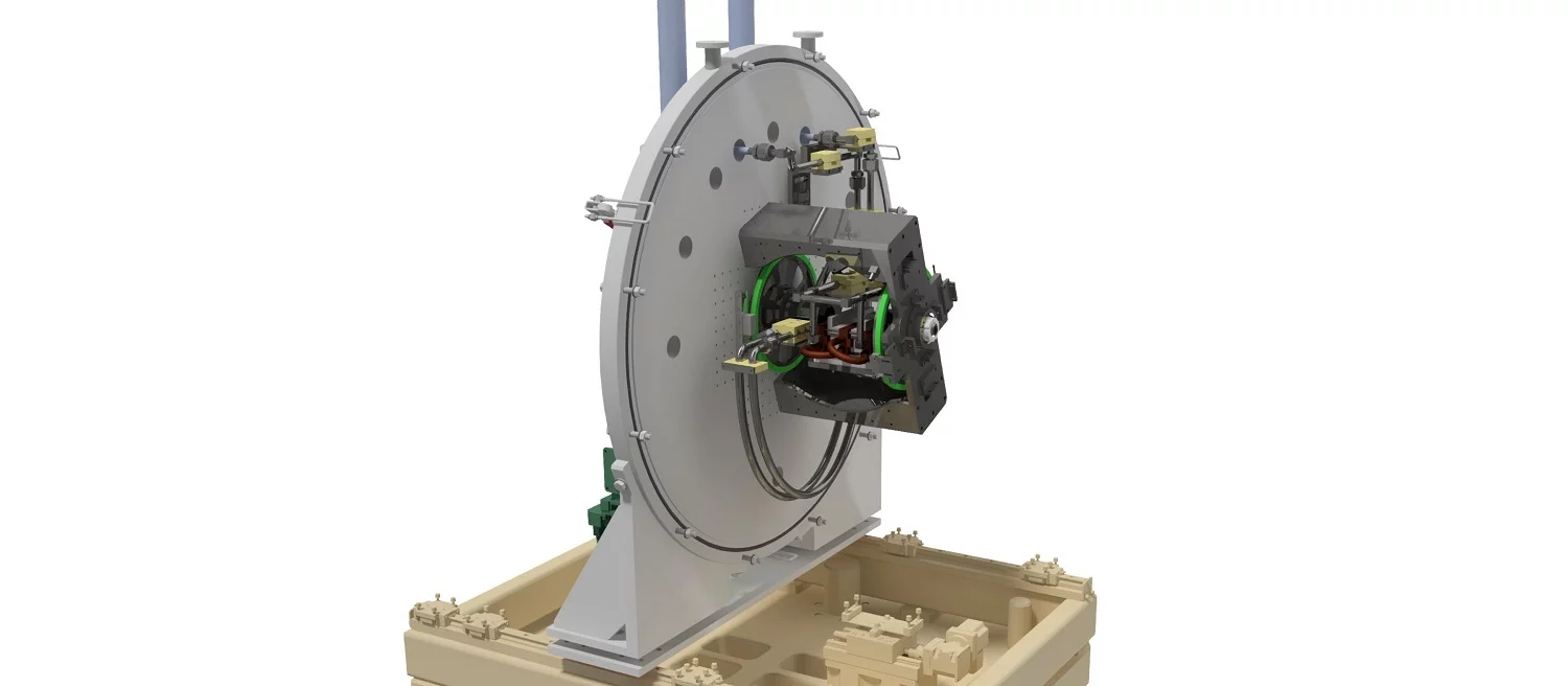
The high stability mirror system is designed to be very robust, reliable and to allow easy access for installation and maintenance. A massive granite block supports the mirrors mechanics/bender and the vessel itself.
The mirrors can be remotely adjusted in five independent degrees of freedom where the translations in X and Y are realized by motorized stages and the rotations (pitch, roll and yaw) are realized by means of virtual motors. The horizontal translation stages allow the selection of different coatings on the mirror. Pt, Rh and Si are available on M1, Pt and Rh on M2. Additionally to the toroids on M2, flat surfaces are available, allowing a wide selection of beam sizes at the sample position.
| Property | Collimating mirror (M1) | Focusing mirror (M2) |
|---|---|---|
| Mirror substrate | Monocrystalline silicon | |
| Shape | Flat, cylindrically bent to tangential cylinder | Sagittal cylinder, cylindrically bent to torus |
| Pitch range | 1.4 mrad to 4.5 mrad (grazing angle) | |
| Optical Coatings |
10 mm (Si) |
23 mm (Rh, torus) |
| Cooling | Max power load 124 W, clamped side water cooling | Passive cooling with copper braids |
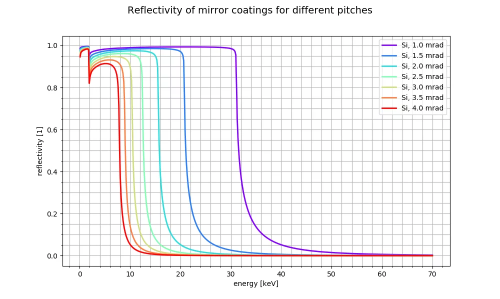
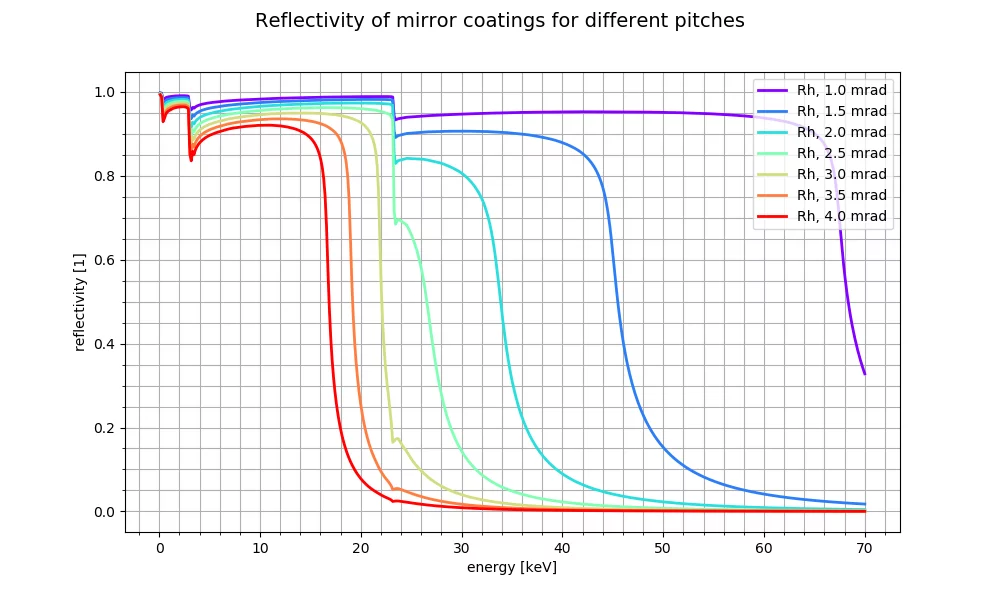
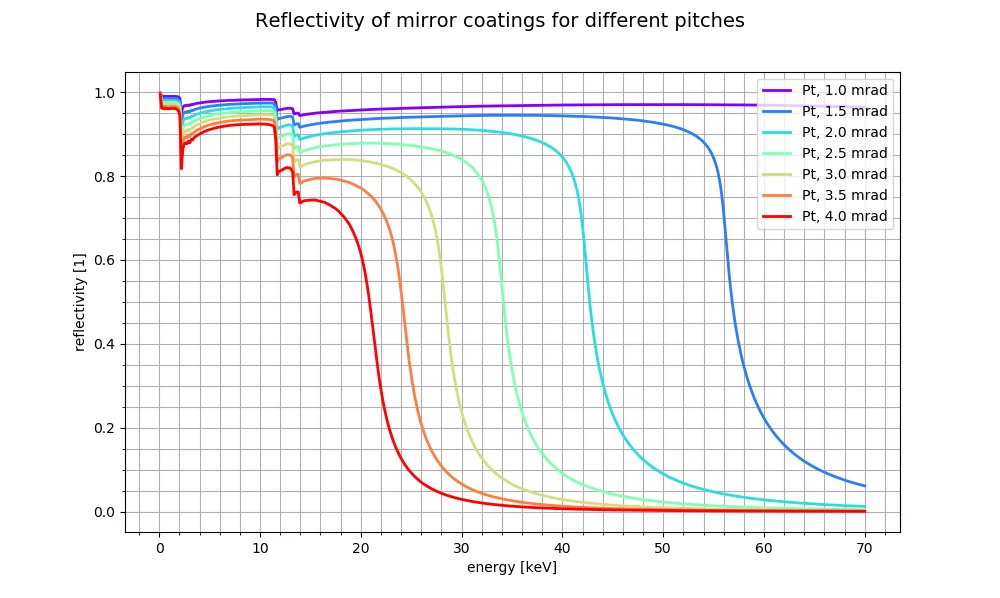
The reflectivities of different mirror pitches are shown below for the mirror surfaces used at Debye. Click on the image to enlarge.
Quick EXAFS monochromator (QEXAFS)
The QEXAFS monochromator consists of two channel cut crystals attached to a direct-drive torque motor. The system facilitates scan speeds for a specific energy range with up to 20 spectra per second (full EXAFS). Additionally, for low concentration samples, the monochromator can be operated in step-scanning mode by using the same motor. The operational energy range can be selected by changing between the Si(111) and the Si(311) crystal and is in the range of 4.5 to 25 keV for the Si(111) and 9 keV to 60 keV for the Si(311). The crystals are cryo-cooled with LN2.
The monochromator is a further development of the proven and successful monochromator initially built by the University of Wuppertal and further developed by PSI.
-
Müller O, Nachtegaal M, Just J, Lützenkirchen-Hecht D, Frahm R
Quick-EXAFS setup at the SuperXAS beamline for in situ X-ray absorption spectroscopy with 10ms time resolution
Journal of Synchrotron Radiation. 2016; 23: 260-266. https://doi.org/10.1107/S1600577515018007
DORA PSI


