Polymer electrolyte fuel cells (PEFC) generate clean electric power through electrohcemical reactions of hydrogen and oxygen gas. PEFCs are considered as one of the powertrains in electric vehicles. The technical challeges of PEFCs (e.g., material degradation, mass transport limitation, and ionic conductivity) stem from an accmulation of product water in internal components. At the imaging beamlines of AMG at SINQ, we are obtaining maps of the water content evolution and distributions in operating PEFCs to enable technological optimisation and pioneer material development for improved performance, lifetime and cost reduction.
Polymer electrolyte fuel cells (PEFC) generate clean electric power through electrohcemical reactions of hydrogen and oxygen gas. PEFCs are considered as one of the powertrains in electric vehicles. The technical challeges of PEFCs (e.g., material degradation, mass transport limitation, and ionic conductivity) stem from an accmulation of product water in internal components. At the imaging beamlines of AMG at SINQ, we are obtaining maps of the water content evolution and distributions in operating PEFCs to enable technological optimisation and pioneer material development for improved performance, lifetime and cost reduction.
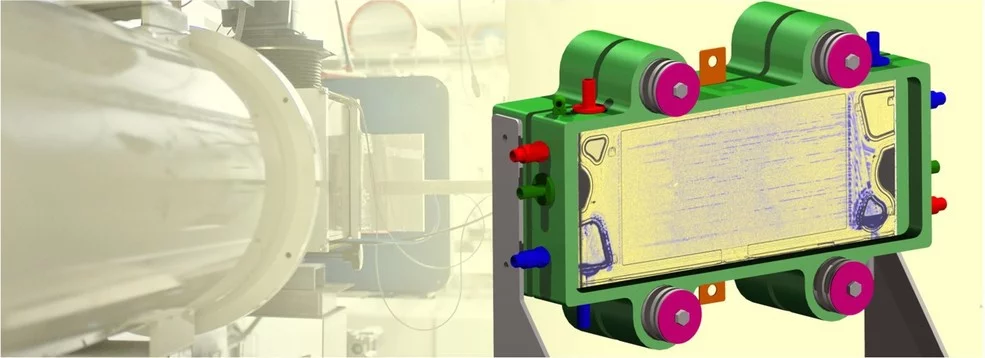
Thermal neutron beams can transmit through many metals without significant intensity reduction (e.g. > 10 cm of aluminum) but they are highly sensitive to water. This leads to high contrast between water and other fuel cell materials, which enables the use of neutron imaging for a variety of purposes inn researching PEFC technology. For example, industrial PEFC stack with 300 cm2 active area are imaged at the NEUTRA beamline to understand the impacts of flow field and inlet/outlet manifold designs (Figure 1), and miniature cells (1 cm2 active area) are imaged at the ICON beamline to resolve water distribution e.g. in a wettability patterned gas dfifusion layer (GDL) [1].
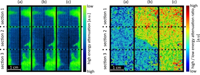
We are thriving to break the boundaries of PEFC and neutron imaging at the same time. One of our recent milestones was to distinguish ice from super-cooled water in PEFCs under sub-zero temperature opeartion conditionns with time-of-flight (ToF) neutron imaging [2]. Neutron cross sections of water in these two states are similar at short neutron wavelengths (< 2Å) but are different at longer neutron wavelengths. At the cold neutron beamline (ICON) a pulsed neutron beam, produced by a rotating chopper disk, is used to exploit the wavelength dependent cross section of super-cooled water and ice. Results are shown in Figure 2 mapping different states of water I operating cells. Another achievement is to apply dark-field contrast neutron imaging in the research on PEFC technology in order to visualize water selectively in the porous layers of the cell, where scattering information of neutrons is superimposed to transmission images recorded with grating interferometers.
Publications
- A. Forner-Cuenca, J. Biesdorf, V. Manzi-Orezzoli, L. Gubler, T. J. Schmidt, P. Boillat “Advanced Water Management in PEFCs: Diffusion Layers with Patterned Wettability III. Operando Characterization with Neutron Imaging” JES. 2016; 163 (13) F1389-F1398
- Siegwart M, Woracek R, Márquez Damián JI, Tremsin AS, Manzi-Orezzoli V, Strobl M, T. J. Schmidt, P. Boillat. “Distinction between super-cooled water and ice with high duty cycle time-of-flight neutron imaging" Review of Scientific Instruments. 2019; 90(10): 103705 (15 pp.).
- M. Siegwart, R. P. Harti, V. Manzi-Orezzoli, J. Valsecchi, M. Strobl, C. Grünzweig, T. J. Schmidt, P. Boillat "Selective Visualization of Water in Fuel Cell Gas Diffusion Layers with Neutron Dark-Field Imaging" JES. 2019; 166 (2) F149-F157
Associated junior researchers
- E.R. Carreon Ruiz, Dr. J.M. Lee
Contact
- Dr. P. Boillat, pierre.boillat@psi.ch, +41 56 310 2743


