Crystal Growth
Travelling Solvent Floating Zone (TSFZ) using an Optical Furnace
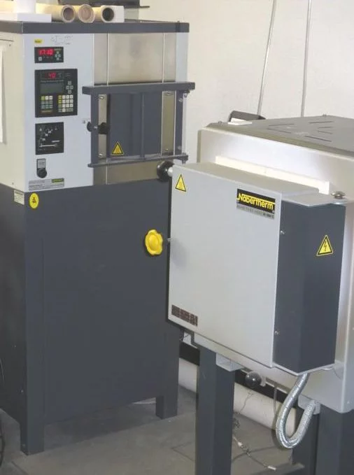
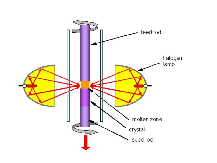
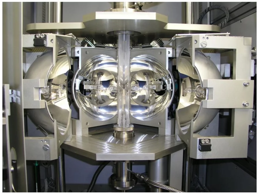
In the Traveling Solvent Floating Zone method a molten zone is formed and held between two solid rods by its own surface tension (see Fig.1). Infrared image furnaces are applied, which enable a focus of the radiation of the halogen lamps into a narrow band around the material. Once a small section of the rod has been melted, the molten (floating) zone is translated by moving the lamps. Crystal material is grown on the solidifying end of the float zone. Fig. 2 shows the photograph of the four mirror crystal growth furnace we are using in the group. The method is crucible free and provides crystals of cm3 volume.
Examples of Crystal Growth
Cuprate spin ladder compounds
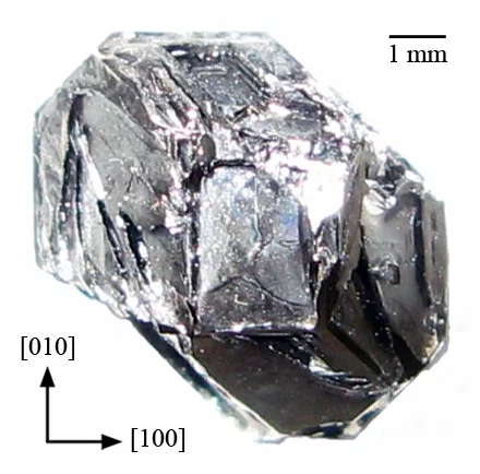
Complex copper oxides (cuprates) with magnetic copper cations (spin ½) creating quasi-one-dimensional patterns in the structure are model systems for quantum magnetism science. A spin ladder can be considered as a chain of antiferromagnetically coupled pairs of spins creating spin dimmers. BiCu2PO6 is a new model compound containing such zigzag copper chains (see Figure 3)
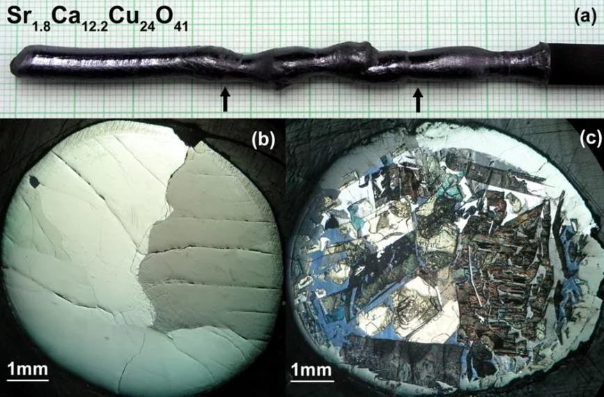
Sr14-xCaxCu24O41 is the only superconducting cuprate containing in the structure only one-dimensional spin ladders (Cu2O3) and chains (CuO) but no typical superconducting copper oxide layers (CuO2).
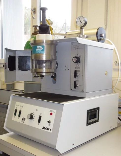
For the first time superconductivity with TC≈12 K was observed for highly Ca-doped samples (x≈13.6) under high hydrostatic pressure of 3-4.5GPa. Crystals with Ca-content x≥12 can be grown by TSFZ method under high oxygen pressure. We have modified the mirror furnace to provide a stable crystal growth at oxygen pressure up to 35bar.
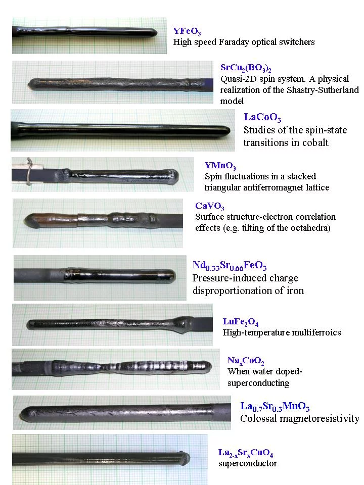
Other Examples of Crystals Grown by the TSFZ Method
Bridgman Method
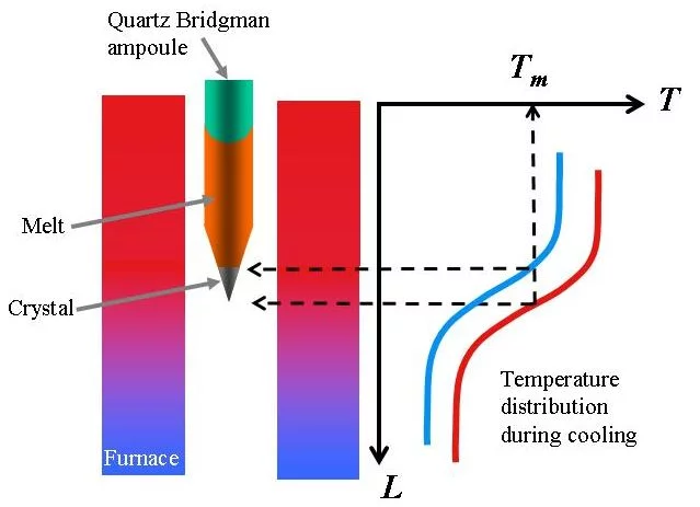
The method is used for materials with congruent (no decomposition at melting point) and relatively low melting temperatures. The polycrystalline material is sealed in quartz ampoule and heated above its melting point in a furnace with controlled temperature distribution. After the material is melted and homogenized during a certain time, the temperature of the furnace is decreased in a controlled way. First the liquid at the “cold” (conical) end of the ampoule starts to solidify and the liquid-solid interface moves up in course of decreasing of the furnace temperature. Fig. 6 presents principle of the method.
Examples of Crystals Grown
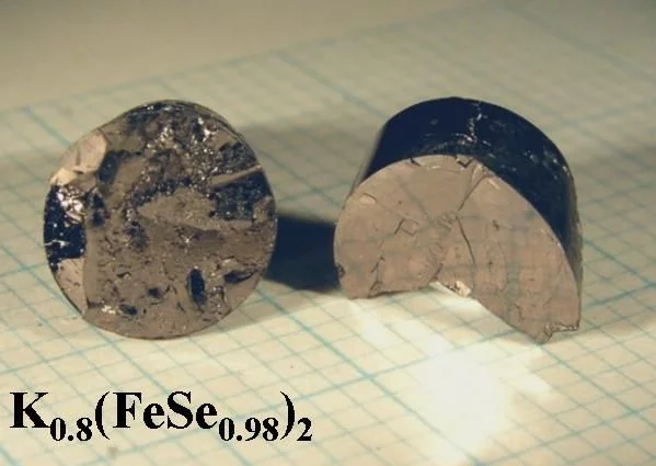
Alkali metal doped iron chalcogenide superconductors
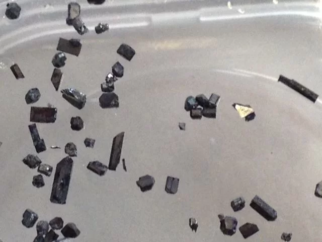
Among the iron-based superconductors discovered in 2008, chalcogenides e.g. FeSe have the simplest layered structure in which Fe cations are tetrahedrally coordinated by Se. The superconducting transition temperature (Tc) of only 8K can be increased to over 30K by intercalation of alkali metals between the FeSe layers. Single crystals were grown in double wall evacuated silica ampoules in vapor of alkali metals (K, Rb, Cs) using FeSe as a precursor. The ampoules were annealed at 1030°C and then cooled down with the rate of 6°C/h.
Among the iron-based superconductors discovered in 2008, chalcogenides e.g. FeSe have the simplest layered structure in which Fe cations are tetrahedrally coordinated by Se. The superconducting transition temperature (Tc) of only 8K can be increased to over 30K by intercalation of alkali metals between the FeSe layers. Single crystals were grown in double wall evacuated silica ampoules in vapor of alkali metals (K, Rb, Cs) using FeSe as a precursor. The ampoules were annealed at 1030°C and then cooled down with the rate of 6°C/h.
Topological Insulators
High-Temperature Solution (Flux) Crystal Growth
The flux method is the crystal growth from high-temperature solutions. The spontaneous crystallization occurs during slow cooling of the solution. Very often it is difficult to separate the crystals from the solvent as well as to avoid contaminations from the crucible material and the solvent. By this method crystal growth commonly occurs at temperature lower than the melting point of the material. This is crucial when the material:- melt incongruently;
- undergoes a phase transition du ring cooling;
- has very high vapor pressure at a melting point
Examples of Crystals Grown by the Flux Method
Other Synthesis Methods
Solid State Synthesis of Polycrystalline Samples
Polycrystalline solids can be prepared from mixtures of solid starting materials. In order for the reaction to occur at an appreciable rate solids have to be heated at high temperatures, often 1000 to 1500°C.
Arc-melting
Melting process used for synthesis of intermetallic compounds at high temperatures (up to 3500°C) in inert gas atmosphere. It applies an arc discharge between a tungsten rod cathode and the metal sample placed on a copper crucible.
Characterization Methods
Structural Characterization: Laue X-Ray Diffraction
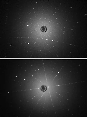
The Laue method is used to determine orientation and quality of single crystals. White (polychromatic) x-ray radiation is transmitted through a crystal. Each set of planes in the crystal structure diffracts the particular wavelength from the white radiation that satisfies the Bragg law. The diffracted beams form arrays of spots recorded by the CCD camera. Details of Laue setup can be found here.Structural Characterization: Powder X-Ray Diffraction
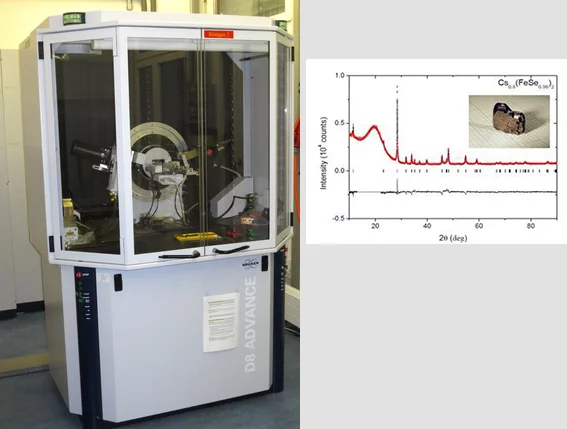
Powder X-ray diffraction is used for:
- Phase identification
- Crystallinity
- Crystal structure determination
- Determine size and strain broadening
Metallographic (Microstructure) Characterization
Metallography is used to study microstructure of the materials typically using microscopy. Single crystal imperfections like domain walls, pores and inclusions can be detected. The surface of an inspected material is prepared by grinding and polishing.
Chemical Composition - Micro X-Ray Fluorescence
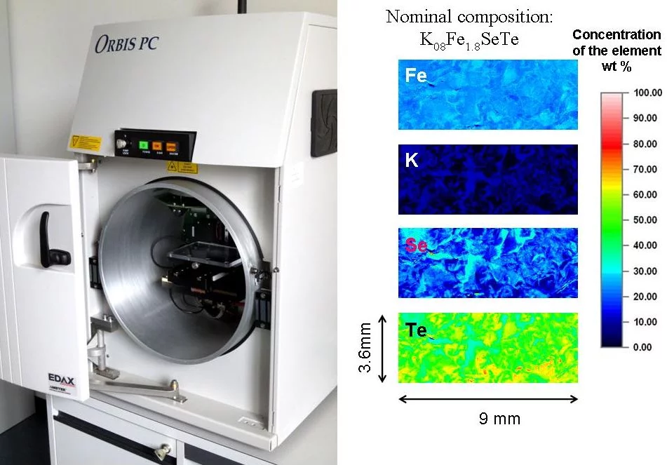
Micro x-ray fluorescence is an elemental analysis technique. It uses x-ray excitation to induce element specific characteristic x-ray fluorescence emission for the elemental analysis. The method allows examination of large sample areas with resolution of 30μm which is a spot of the focused primary x-ray beam. The method works excellently both with non conductive and conductive samples, requires no high vacuum and is not only surface-sensitive.
Thermal Analysis
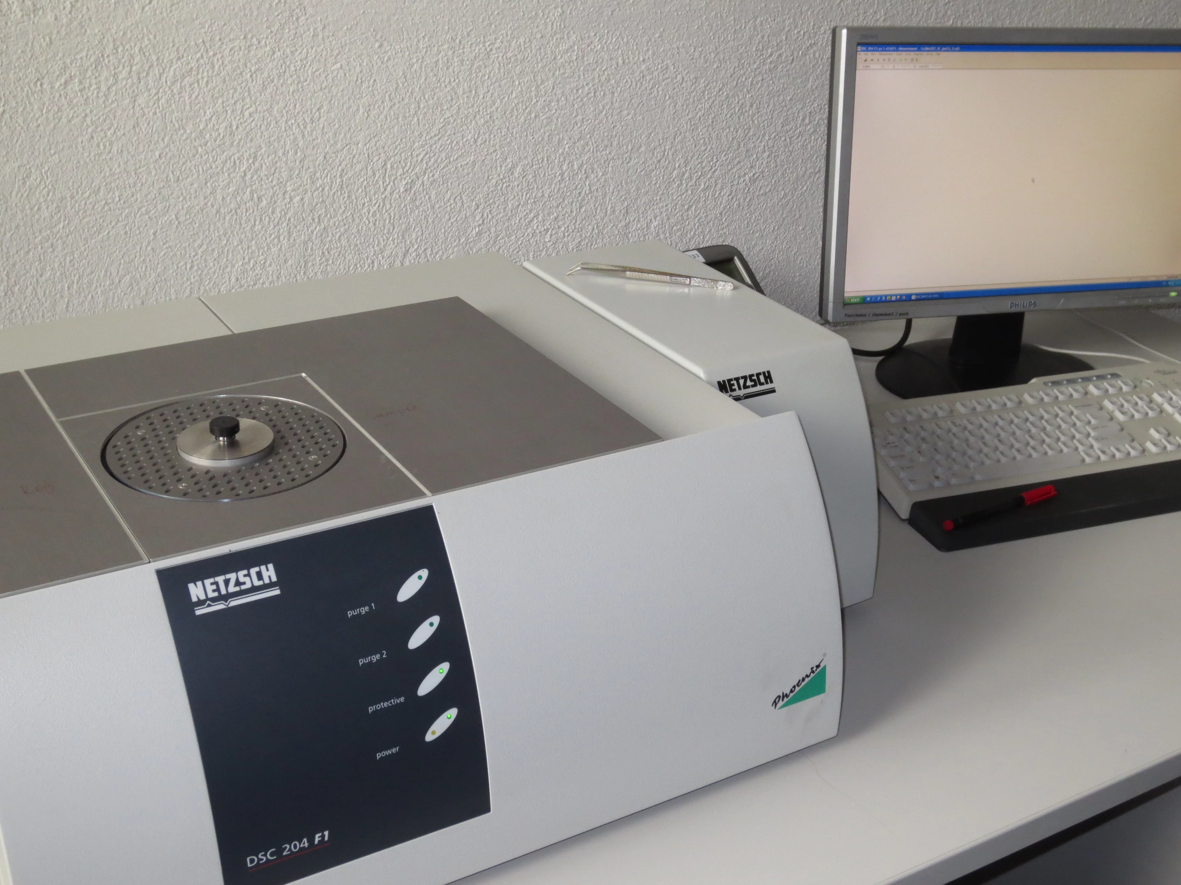
Differential scanning calorimetry or DSC is a thermoanalytical technique in which the difference in the amount of heat required to increase the temperature of a sample and reference is measured as a function of temperature. The result of a DSC experiment is a curve of heat flux versus temperature or versus time. This method is used to detect phase transitions in the sample.
Thermogravimetric Analysis (TGA)
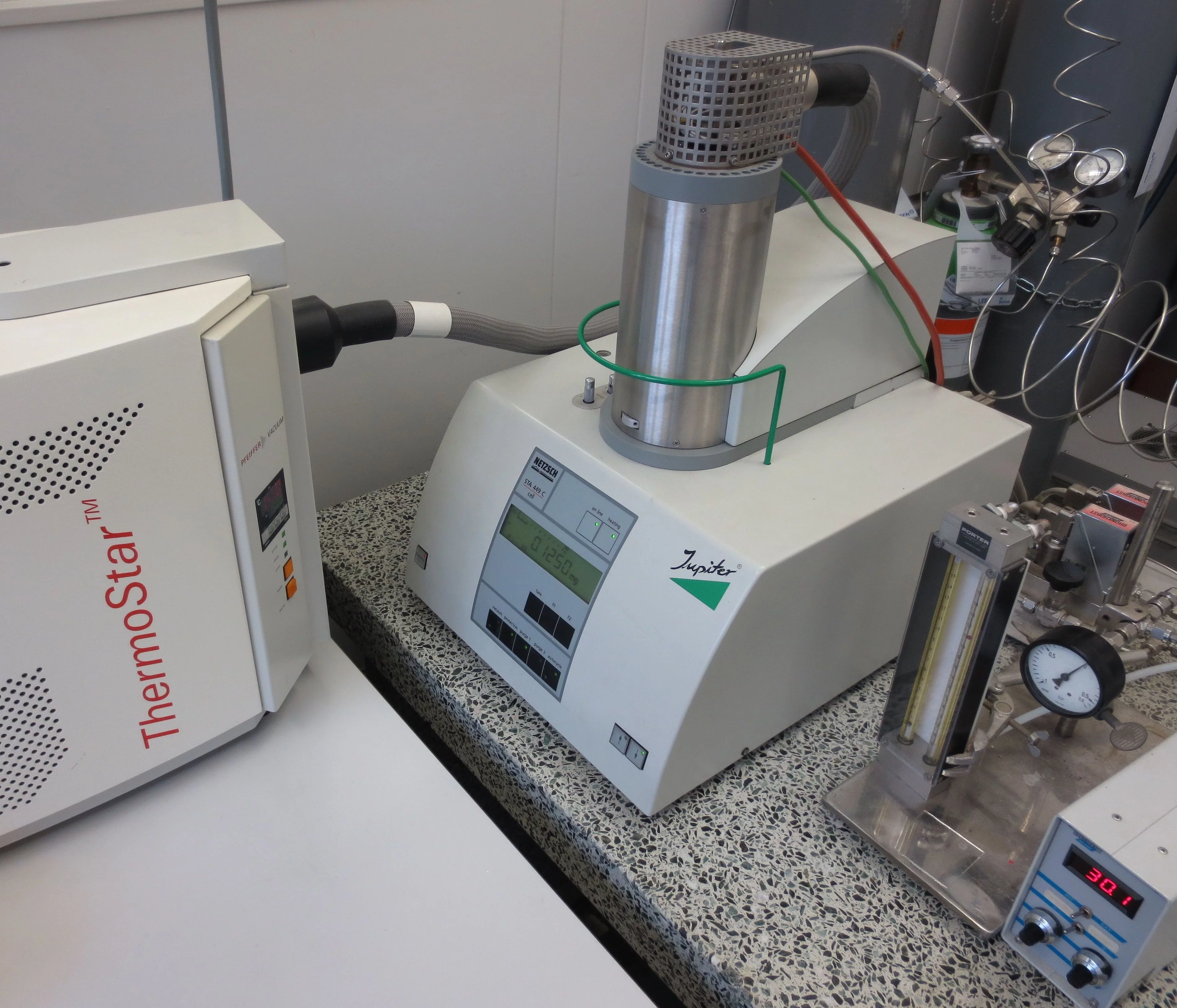
TGA is a method of thermal analysis in which changes in physical and chemical properties of materials are measured as a function of increasing temperature (with constant heating rate). TGA is commonly used to determine selected characteristics of materials that exhibit either mass loss or gain due to decomposition, oxidation, or loss of volatiles (such as moisture).
Contact
Solid State Chem. Group
Laboratory for Multiscale materials eXperiments
PSI
CH-5232 Villigen PSI
Switzerland
Head of Group
Dr. Ekaterina Pomjakushina
+41 56 310 32 07
ekaterina.pomjakushina@psi.ch
Homepage CNM
Research with Neutrons and Muons NUM Division at PSI
Open Positions
Job Opportunities at Research Division NUM.PSI Scientific Reports
Archive 2006-2012. The Scientific Reports – containing accounts of research topics from all the different areas – provide an impression of the variety of subjects researched at PSI.

![Fig. 3 (a) Crystal structure of BiCu2PO6; (b), (c) the coupled two-leg zigzag ladders formed by two different Cu [Cu1 (red) and Cu2 (orange)] and O [O1 and O2] atoms run along the crystallographic b-axis.](/sites/default/files/styles/primer_teaser_grid_16_9_scale_md/public/import/lmx-ssc/MaterialsLab2EN/Fig3.jpg.webp?itok=TQCgkc6E)

