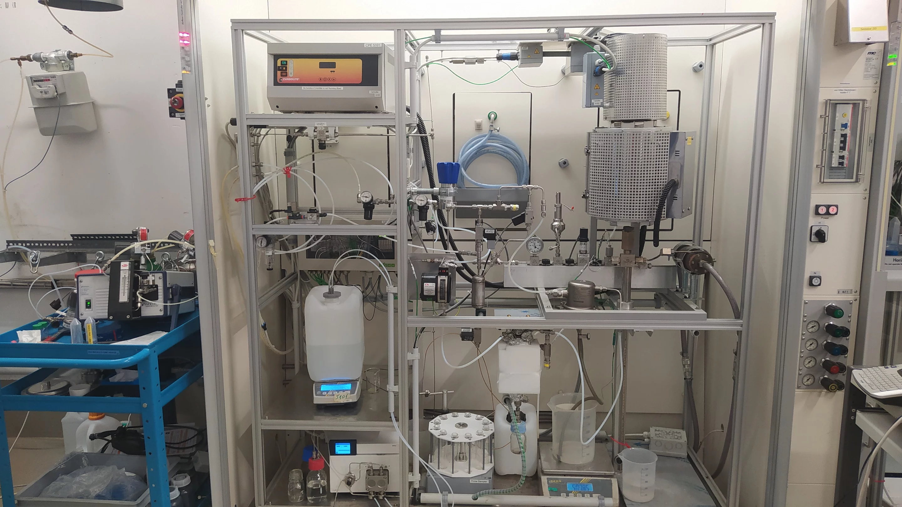
Direkt zum Inhalt
  • Paul Scherrer Institut PSI
  • PSI Research, Labs & User Services

Digital User Office

  • Digital User Office
  • DE
  • EN
  • FR
Paul Scherrer Institut (PSI)
Suche
Paul Scherrer Institut (PSI)

Hauptnavigation

  • Research at PSIÖffnen dieses Hauptmenu Punktes
    • Research Initiatives
    • Ethics and Research integrity
    • Scientific Highlights
    • Scientific Events
    • Scientific Career
    • PSI-FELLOW
    • PSI Data Policy
  • Research Divisions and LabsÖffnen dieses Hauptmenu Punktes
    • Overview
    • Research with Neutrons and Muons
    • Photon Science
    • Energy and Environment
    • Nuclear Energy and Safety
    • Biology and Chemistry
    • Scientific Computing, Theory and Data
    • Large Research Facilities
  • Facilities and InstrumentsÖffnen dieses Hauptmenu Punktes
    • Overview
    • Large Research Facilities
    • Facilities
    • PSI Facility Newsletter
  • PSI User ServicesÖffnen dieses Hauptmenu Punktes
    • User Office
    • Methods at the PSI User Facilities
    • Proposals for beam time
    • Proposal Deadlines
    • Data Analysis Service (PSD)
    • EU support programmes
  • New ProjectsÖffnen dieses Hauptmenu Punktes
    • SLS 2.0
    • IMPACT
  • DE
  • EN
  • FR

Digital User Office (mobile)

  • Digital User Office

Sie befinden sich hier:

  1. PSI Home
  2. Labs & User Services
  3. ENE
  4. LBK
  5. CPE
  6. Test Rigs

Sekundäre Navigation

Catalytic Process Engineering

  • About CPE
  • HydroPilot
  • People
  • Projects
    • KONTI-C
    • In-situ characterization of catalysts under HP/HT conditions
    • SNG
    • Etamax
    • Biomass related Salt Solutions
    • Rational Design of Novel Ru/C Catalysts for Supercritical Water Gasification (SCWG)
    • In-situ characterization of catalysts
    • Green chemicals from Lignin
  • Fuel Simulation
  • Analytics
    • TG FTIR
    • FTIR-Raman
  • Test Rigs
  • Publications
    • Articles
    • Poster
    • Talks
    • Books chapters
    • Dissertations

Info message

Dieser Inhalt ist nicht auf Deutsch verfügbar.

Test Rigs

Salsan-II
Salsan-II

Salsan-II

Description

The Salsan II rig was build in the winter 2014/2015. Central to the set-up is a dip-tube salt separator. The special "zircalloy" vesel originally designed for the 2005 salsan campain by Andrew Peterson was re-used. In this previous study, salt separation was visualised using neutron radiography. Zircalloy was used as construction material as it is transparent for neutrons.

The objective of this set-up is to study the separation and deposition of salts under hydrothermal conditions and to obtain data that complement CFD simulations of the flow inside the salt separator.

Characteristics of the set up

  • Up to 320 bar
  • T max. 450°C
  • V* = 20 ml/min.
  • Vessel volume ca. 50ml
  • 9 individually controlled vessel heaters

Konti-C
Konti-C

KONTI C

Mobile gasification plant. For more information see the project page KONTI C

Features of KONTI C:

  • Microalgae pumped as a slurry (10 - 20 wt. % of DM) at 1 kg/hours
  • Pressure max = 40 MPa
  • Temperature max = 550 °C
  • New salt separator design (patent filed)
  • Gaseous effluents analysed online by a MicroGC
  • Liquid effluents analysed online by TOC and conductivity
  • Highly automated (liquid sampling, temperature profile measurements) and remote controlled.

Konti-1
Konti-1

KONTI I

The continuously operating catalyst test rig is built for catalyst long term testing. As two HPLC pumps are responsible to provide system pressure, only liquids can be used as reactants. A mixture of several substances simulates liquefied biomass. The ratio of biomass to water can be chosen as they are fed separately and mixed only later in the plant. The biomass enters the mixing chamber cold and the feed tubing is gold plated to eliminate the possibility of reaction inside the steel tube due to alloys that might exhibit catalytic activity. The water is heated to the desired temperature before mixing.

The biomass-water-mixture is sent to the reactor that can be filled with different types of catalysts to be tested. After a pressure regulation valve and a phase separator, the liquid products can be examined with our TOC apparatus in terms of carbon content or in our HPIC to identify chemical compounds. The gas is sent to a gas chromatograph and is being analyzed it in a continuous way.

Characteristics:

  • Liquid biomass model substances
  • Pmax 40 MPa
  • Tmax 550 °C
  • Ratio biomass / water variable
  • Long-term catalyst stability testing possible
  • Online GC analyses, offline TOC and HPIC analyses by sampling

Konti-II
Konti-II

KONTI II

A Small Scale Process Demonstration Unit (PDU)

The KONTI-2 is a continuously operating laboratory plant built to demonstrate the process of the hydrothermal gasification of real biomass to methane and carbon dioxide. A hydrothermal environment (conditions of subcritical or supercritical water, 25-35 MPa and 350-450 °C) is used for the gasification because biomass with a high water content or organic containing waste waters serve as feed. Unfortunately no slurries can be fed due to the small scale of the PDU (feed stream about 1 kg/h - there is no pump available which is able to pump slurries at that scale), so liquid biomass has to be used.

The LabVIEW™ program is used to monitor pressures and temperatures to control the heaters and to switch the pumps.

The plant consists of seven sections:

  • Feeding: The biomass is pumped from a stirred isothermal tank via a booster pump and a high pressure pump into the plant.
  • Preheating: The biomass is heated up to preheat it and to hydrolyze larger biopolymers into smaller molecules.
  • Salt separation: Removal of dissolved salts by precipitation through heating up the feed stream to supercritical temperatures.
  • Gasification: Gasification of the biomass to methane and carbon dioxide in a fix bed reactor filled with a catalyst under near critical or supercritical conditions.
  • Cooling and pressure regulation: After the reactor the product stream is cooled to about 50 °C. The pressure is regulated via and control valve and a relief valve where the product stream is expanded to atmospheric pressure.
  • Phase Separation of the gaseous and the aqueous phase. The gaseous product then pass a condenser to remove water vapour.
  • Analysis and exhaust gas combustion: Online GC analysis of the gaseous products and combustion of inflammable gases before venting into the air.

Sapphire cell
Sapphire cell

Sapphire Window Cell

For optical observation of phase transitions in hydrothermal salt solutions, we are using a high pressure, high temperature cell with two sapphire windows, manufactured by SITEC. With this setup we perform measurements up to 400°C and 350 bar. The cell is filled and pressurized with a syringe pump (ISCO) and can be used in flow-through and bypass mode. Measurements are performed with the synthetic method either isobaric or isothermal.

Characteristics:

  • Pmax 35 MPa
  • Tmax 400 °C
  • Sapphire windows
  • Optical width 8 mm Ø

High-Pressure Reaction Cell / DRIFTS set-up

Suitable for in situ investigations of catalytic experiments using pulverised commercial catalysts. The experiments are performed under fixed-bed and gas-flow conditions (max. gas flow: 50 ml/min). We are using several High-Pressure Reaction cells, but in use is mainly the following set-up: Modified Environmental Chamber (HT-HP-EC 19933) together with SELECTOR Diffuse Reflectance Accessory by Graseby-Specac.
DRIFTS cell
DRIFTS cell
DRIFTS cell with optic
Plan of the optic
Plan of the optic

Drifts Set Up
Drifts Set Up

Characteristics:

  • Sample volume: approx. 80 mg catalyst
  • Pmax : 11 Bara
  • Tmax: 500 °C - heating rates: up to 5 K / min
  • Window: ZnSe (transparent from 20'000 cm-1 to 455 cm-1)
  • On line analysis of the reactant and product gas composition possible with QMS

High Pressure Autoclave

High Pressure Autoclave

The autoclave is suitable for performing reactions in a high temperature pressurized environment. It is equipped with a gas inlet stirrer so there is an ideal mixing of the reactants even if the reaction mixture is multi phase system, e.g. a gaseous, a liquid an a catalyst phase. Temperature and pressure within the autoclave are detected online. Therefore the autoclave can be used to measure reaction kinetics for reactions with gaseous reactants or products. Currently the autoclave is used to study the methanation reaction and the water gas shift reaction in supercritical water in the presence of a heterogeneous catalyst.

Characteristics:

  • Volume = 422 ml
  • Pmax = 325 bar
  • Tmax = 500 °C
  • Online detection of temperature and pressure

Neutron image of the vessel. The salts on the botton are shown dark.

Salsan

Vessel for the separation and precipitation of ionic species from supercritical water. This vessel has been built from nuclear-grade Zircaloy-2, which renders it nearly invisible to neutrons. Because of this, neutron transmission radiography can be used to visualize the precipitation and transport behavior inside of the vessel while it is operating at high-temperatures and pressures.

The vessel is built in a continuous flow system with the following characteristics:

Fed with a pulseless HPLC pump capable of 1-10 mL/min Preheater capable of heating the feed to 350C, maintaining the fluid at slightly subcritical conditions so that precipitation does not occur before the Salsan vessel. Separate heater controls for the top and bottom of the vessel. In normal operation, the bottom zone is kept at a lower temperature to allow brine to accumulate in this zone. The top zone is kept supercritical for salt separation. Online monitoring of conductivity for indication of salt removal efficiency. The vessel is constructed so that fluid enters in the top through a dip-tube. The fluid flow reverses as it is heated to supercritical conditions. Meanwhile, salts precipitate either as solids or as a brine and settle to the bottom of the vessel.


Figure 1: Top: 3-D model of the in-situ reactor. 1: safety shield, 2: aperture for X-ray beam, 3: X-ray beam, 4: coil of copper tubing for water cooling, 5: stainless steel casing, 6: coil of heating wire, 7: aluminum nitride tube, 8: thermocouple, 9: stainless steel frit, 10: catalyst bed. Bottom: Photographs of assembled in-situ XAS reactors with and without installed water cooling.

Catalytic reactor for in-situ XAS under supercritical water conditions

A catalytic reactor for in-situ XAS under supercritical water conditions was constructed from aluminum nitride (see Figure 1). This material presents a mechanical strength similar to sapphire and exceptionally high heat conductivity. Furthermore, it transmits X-ray radiation without causing diffraction, due to its polycrystalline nature. The tubular design, where the entire reactor is made of aluminum nitride, has a clear advantage over window-type reactors: it allows for spatial resolution along its entire length.
Figure 2: Calculated X-ray transmission of an AlN capillary with a wall thickness of 1.25 mm (hence, a material thickness of 2.5 mm).
The reactor can be used at pressures of up to 300 bar and temperatures of up to 450°C. This allows for reaching the supercritical state of most gases and liquids, including water. It was pressure-tested at 300 bar at room temperature for 3 hours in our high pressure lab and operated almost continuously at 245 bar and 400°C for 5 days. During that time, no material failure occurred, nor could any degradation of the reactor material be observed. An electrical power of 120 W was sufficient to heat the catalytic zone of the reactor to 400°C at a rate of 4 K/s whilst water was fed at a flow rate of 0.5 ml/min. Since aluminum nitride has a high temperature shock stability, experiments involving fast heating-cooling cycles are not expected to present a problem.


The batch vessel
The batch vessel

Batch Hydro I + II

The batch reactor is suitable to pre-test catalysts for activity or carrying out biomass liquefaction and gasification experiments. An advantage is that real biomass can be used whereas in the continuous reactor we built so far only liquids can be used (model substances).

Characteristics:

  • Volume approx. 30 mL
  • Pmax 40 MPa
  • Tmax 550 °C
  • Possibility of addition of inert gas (larger pressures possible)
  • Heating by immersion into fluidized sand bath (heat up rates 5 – 40 K / min)
  • Quenching after reaction by immersion into water bath
  • No online analysis of reactants and products possible during reactio

Lab setup of channel reactor with the feed system (left side of picture), channel reactor (in the middle of the picture), heating box for sampling capillary (right side of picture) and the infrared camera (top section of the picture)

Benkin

Feed System Water and Gasoline are fed using pressurised containers and LiquiFLOW™ controllers Oxygen and nitrogen are fed through flow controllers 2 Separate evaporators for water and gasoline Superheater up to 750°C

Reactor Stainless steel, channel height = 4 mm Maximum heating temperature = 750°C

Gas Sampling Movable stainless steel sampling capillary, internal diameter = 0.5 mm, external diameter = 0.8 mm Capillary enters reactor through high temperature septum port Capillary is placed directly above catalyst plate Electrical step motor is coupled to a linear positioning system (accuracy < 0.1 mm) Heated transfer line to GC and MS

Setup Control LabVIEW™ program to control the step motor, the mass flow meters and the controllers of the different heaters

Infrared Camera
  • Spectral range: 900 - 1700 nm
  • Detector: Indium Gallium Arsenide
  • Array format: 320 x 256
  • Pixel: 30 x 30 microns
  • Frame rate: 30 Hz
  • Temperature range: 20 - 1200°C

Mit Sidebar

Contact

Paul Scherrer Institut
Bioenergy and Catalysis Laboratory
5232 Villigen PSI
Switzerland

Head CPE Group
Prof. Dr. Frédéric Vogel
Tel: +41 56 310 21 35
Email: frederic.vogel at psi.ch

Secretary
Gisela Herlein
Tel: +41 56 310 26 63
E-mail: gisela.herlein@psi.ch

Homepage ENE

Energy and Environment Research Division at PSI

fhnw logo de.png

The College of Engineering of the University of Applied Sciences Northwestern Switzerland

PSI Scientific Reports

Archive 2006-2012. The Scientific Reports – containing accounts of research topics from all the different areas – provide an impression of the variety of subjects researched at PSI.


ENE Open positions

current opening at Research Division Energy and Environment


top

Fussbereich

Paul Scherrer Institut

Forschungsstrasse 111
5232 Villigen PSI
Schweiz

Telefon: +41 56 310 21 11
Telefax: +41 56 310 21 99

Der Weg zu uns
Kontakt

Besucherzentrum psi forum
Schülerlabor iLab
Zentrum für Protonentherapie
PSI Bildungszentrum
PSI Guest House (in english)
PSI Gastronomie
psi forum-Shop


Service & Support

  • Telefonbuch
  • User Office
  • Accelerator Status
  • Publikationen des PSI
  • Lieferanten
  • E-Rechnung
  • Computing
  • Sicherheit

Karriere

  • Arbeiten am PSI
  • Stellenangebote
  • Aus- und Weiterbildung
  • Career Center
  • Berufsbildung
  • PSI Bildungszentrum

Für die Medien

  • Das PSI in Kürze
  • Zahlen und Fakten
  • Mediacorner
  • Medienmitteilungen
  • Social Media

Folgen Sie uns: Twitter (deutsch) LinkedIn Youtube Facebook Instagram Issuu RSS

Footer legal

  • Impressum
  • Nutzungsbedingungen
  • Editoren-Login