Optical elements
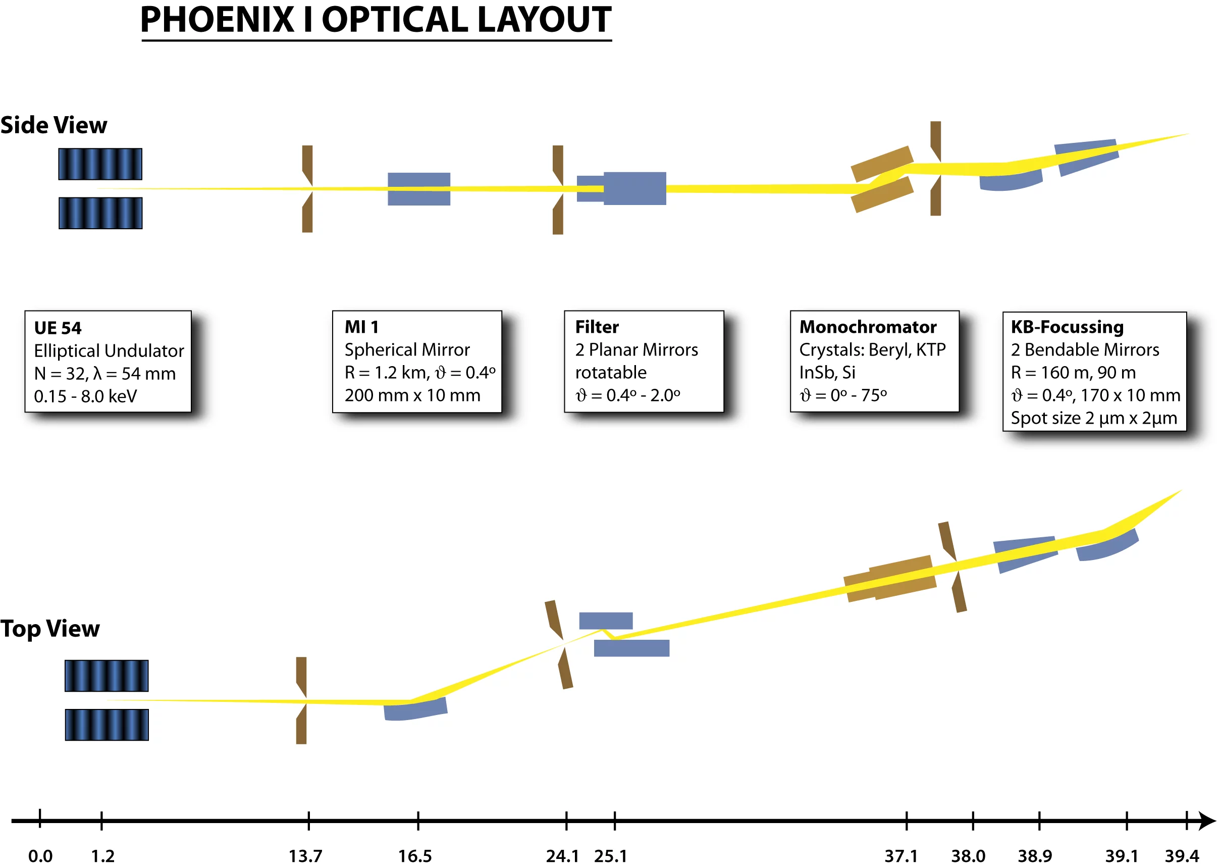
The optical elements of the Phoenix I beamline and their functions are shown in the figure below.A spherical mirror (MI 1) provides a demagnification of the horizontal source size by more than a factor of two. The new horizontal image point is then imaged into the final spot with the help of the second focussing mirror (last mirror of the beamline). The vertical focus is obtained by the first focussing mirror that demagnifies the source directly. Both mirrors are arranged in Kirkpatrick-Baez configuration and have bendable plane mirrors. Two plane rotatable mirrors allow the suppression of higher harmonics. A double crystal monochromator equipped with four different crystal pairs provides the monochromatic beam.
Mirrors
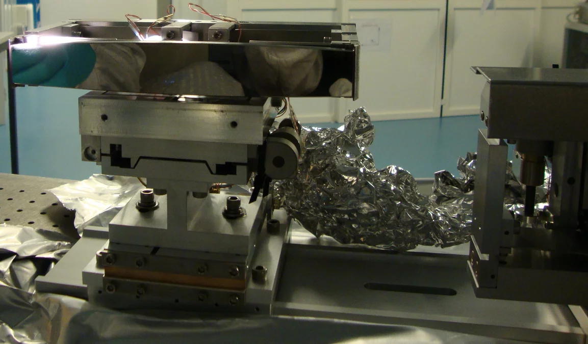
All the mirrors of the Phoenix I beamline are made of fused silica and are coated with a 30 nm thick layer of Nickel. They provide the focussing of the beam and a rejection of higher orders.
The first mirror (MI 1) demagnifies the horizontal source size by a factor of 2.2 into an intermediate focus. This mirror has a spherical shape with a radius of curvature of 1.2 km. The grazing incidence angle is 0.4º which results in a cut-off energy of 8.1 keV. The mirror is water-cooled and can be oriented along 2 translational axes (x, y) and 3 rotational axes (roll, pitch, and yaw). An adjustable aperture in the intermediate focus allows to reduce the final focal horizontal size.
The filter system consists out of two planar mirrors that rotate around a common axis. This system is used to suppress any higher-order contamination of the beam. The obtainable grazing incidence angle is 0.4º - 1.6º which corresponds to cut-off energies of 8.1 keV - 2.1 keV. In addition to the rotation the whole system can be translated transversely. Both mirrors are water cooled.
The final focus spot is obtained with two mirrors arranged in a Kirkpatrick-Baez configuration. Both of them have a grazing incidence angle of 0.4º. The first mirror focuses vertically by a factor of 70. The resulting vertical spot size is limited by the slope errors and quality of the mirror and is about 2 µm. The second mirror focuses horizontally the image from the intermediate focus by a factor of 50 which results in a horizontal spot size of bout 2 µm. It can be reduced by about a factor of two at the cost of flux by reducing the aperture in the intermediate focus. Both mirrors can be adjusted in pitch and roll as well as horizontally and vertically.
Double-crystal monochromator
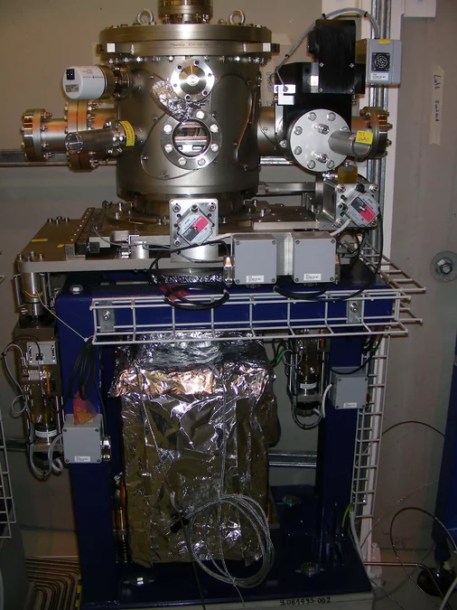
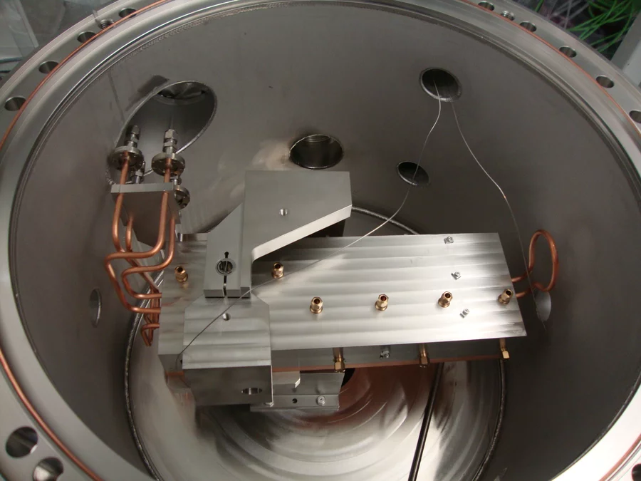
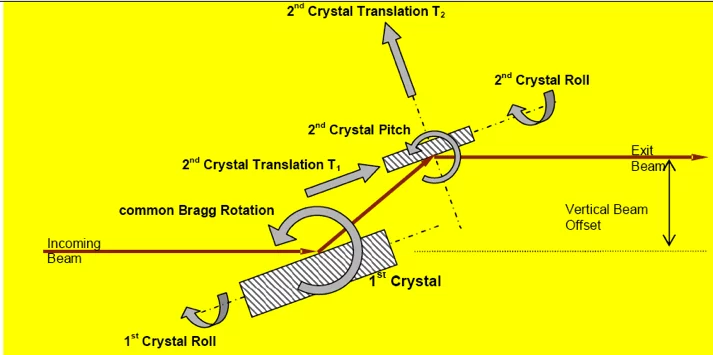
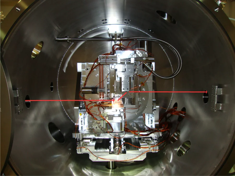
The double crystal monochromator (DCM) consists of four crystal pairs -depending on the energy range- which are precisely positioned and oriented in the X-ray beam.
| Crystal | Energy Range (eV) |
|---|---|
| Si (111) | 2100 - 8000 |
| InSb (111) | 1720 - 3700 |
| KTiOPO4 (011) | 1200 - 2100 |
| Beryl (10-10) | 800 - 1550 |
Two successive Bragg reflections direct photons of the desired energy parallel to the incoming beam direction, but offset upward by 25 mm. Changes in photon energy require a translation of the second crystal along two axes (T1, T2) such that the offset of the outgoing beam stays constant ("fixed exit" configuration).

