


PANDA Large-scale Experiments addressing Complex Natural Circulation in a PWR two-room type containment
The thermal-hydraulic processes during a postulated severe accident in a nuclear power plant are very complex. The associated physical phenomena such as high velocity jets at the break location, large plumes impinging on internal structures, condensation, and re-evaporation of steam as well as hydrogen and aerosol release and transport result in a large variety of length and velocity scales.
The safety analyses is carried out using advanced computational tools including CFD codes, which requires extensive validation using detailed measurements obtained in in large-scale multi-compartment facilities with CFD-grade instrumentation.
The OECD/NEA HYMERES project (https://www.psi.ch/en/teg/projects) was carried out to create an experimental database consisting of 24 PANDA tests and 9 MISTRA tests (CEA, France) addressing phenomena considered to have high safety relevance. The test specifications, e.g. initial and boundary conditions and the spatial and time resolution of the instrumentation were defined to enhance the PANDA data suitability to assess and validate the computational tools.
In two PANDA tests (HP6_1, HP6_2) for the first time in a large-scale multi-compartment facility, was studied the effect of complex natural circulations that would form in the so called “two-room type containment” on hydrogen distribution [1].
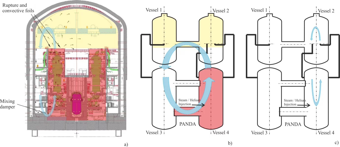
In some PWR containments (e.g. KONVOI, EPR, etc.), during normal operation the overall containment volume can be considered consisting in “two-zones or rooms”, an “inner inaccessible zone or room” (marked in red in Figure 1), and an “outer accessible zone or room” (marked in yellow and white in Figure 1).
During a postulated Loss of Coolant Accident (LOCA) with release of steam in the inner zone the pressure difference created between the two zones determines the passive opening of rupture and convective foils located at the top of the Steam Generator towers and it is predicted that large flow loops would be established between the inner and the outer zone. Some PWR designs, e.g. EPRTM type are equipped also with “dampers” between the bottom of the annular region and the inners rooms (as shown in Figure 1). The effect of large-scale natural circulation in a postulated accident scenario with release of hydrogen is to homogenize the distribution of hydrogen and therefore to mitigate the risk associated with high hydrogen concentration that could lead to combustion or detonation inside the containment.
The objectives of the HP6_1 and HP6_2 tests were twofold. To reproduce, as much as possible, the main features of the containment response for the aforementioned idealized accident scenarios, and to create an experimental database suitable for the assessment of advanced computational tools for the analysis of the flow transport in a multi compartment containment.
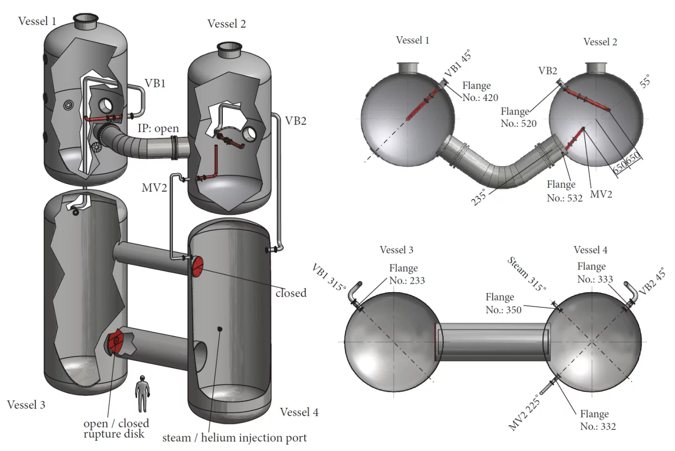
The test HP6_1 and HP6_2 had the same thermal-hydraulics initial and boundary conditions. The only difference between the two tests is the presence or absence of an opening in the lower interconnecting pipe between Vessels 3 and 4 (see Figure 2), and this difference allowed to study EPRTM type features in the HP6_1 test and KONVOI type features in the HP6_2 test.
The main challenge for the definition of PANDA tests was to reproduce in PANDA representative transients of real PWR containment, in spite of the deviations that are associated with the different geometries. Therefore, scoping calculations using GOTHIC and APROS computational tools aimed to investigate which facility configurations and initial and boundary conditions were required to ensure that the PANDA tests would result in conditions of interest for assessing the capability of the codes to simulate the mixing produced by large-scale circulation in a real containment.
To establish similarity between the PANDA tests and the transient scenario expected in a real containment, the conceptual design of the tests has been achieved with two steps [2]:
Step 1: to consider an example of analysis of an accident for a generic containment, using information from open literature and to identify key important features of the postulated accident scenarios;
Step 2: to identify the PANDA configurations using four vessels and existing lines and considering feasible modifications of the facility (e.g. implementation of new lines, or components) in such a way that phenomena taking place in PANDA tests were suitable to represent the key-important features identified in step 1 for the generic containment.
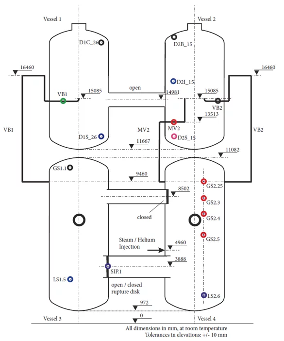
In Figure 2 is shown a 3D rendering of the PANDA facility configuration used for the HP6 series, and red are identified the new lines and components were implemented based on the above step 2. In Figure 3 is a 2D schematic with the locations of selected sensors used to characterize the test phenomenology.
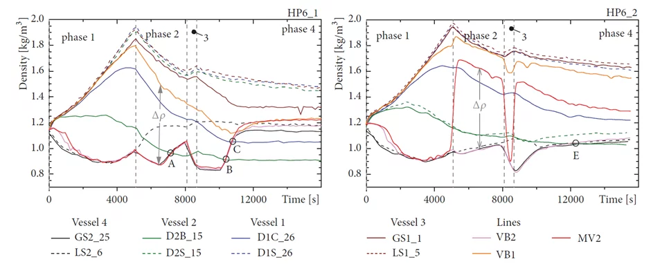
The experimental results permitted the complex natural circulation phenomena during the four phases of HP6_1 and HP6_2 and the detailed description has been published in [1].
In Figure 4 are plotted the density as a function of time for selected locations in all for vessels for experiments HP6_1 (left) and HP6_2 (right). Legend nomenclature refers to locations depicted in Figure 3.
Contact
Experimental Thermal-Hydraulics Group (TEG)
Laboratory for Reactor Physics and Thermal-Hydraulics (LRT)
Nuclear Energy and Safety Research Division (NES)
Paul Scherrer Institut
Original Publications
R. Kapulla, G. Mignot, S. Paranjape, D. Paladino
Large Scale Experiments Representing a Containment Natural Circulation Loop During an Accident Scenarios
Science and Technology of Nuclear Installation, 2018.
M. Andreani, D. Paladino, D. Papini
Multi-Step Planning Calculations with the GOTHIC Code Used for the Design of Complex Experiments in the PANDA Facility.
Nuclear Engineering and Design, Volume 339, Pages 116-125, 2018.
H. Dimmelmeier, J. Eyink, and M.-A. Movahed,
Computational validation of the EPR_ combustible gas control system
Nuclear Engineering and Design, vol. 249, pp. 118–124, 2012.