Monte Carlo Simulation of Scintillation Detector for Spent Fuel Characterization in a Hot Cell
Energy and Environment Nuclear Power Plant Safety
The study of spent fuel is one of the prerequisites for the improvement and technological evolution of NPPs. The analysis of material degradation in the reactor, the measurement of radiation levels, and the decommissioning of the system are strongly supported by the characterization of spent fuel. For the latter case (back end), this generally includes the measurement of the radioactive source terms (mainly neutron and gamma) and the corresponding heat load. Both the intensity and the radial and axial distributions of the different radioactive isotopes in spent fuel rods are of interest. The diversity of fresh fuel designs and operating conditions in nuclear power plants dictates that the spent fuel source term must be predicted in many conditions, which cannot reasonably be done experimentally. Instead, spent fuel source terms are measured for a limited number of fuel/operating conditions and predicted by depletion codes in any other conditions. Nevertheless, the validation of these codes with experimental results is necessary, requiring accurate detection systems to provide data.
At the Paul Scherrer Institute (PSI), the characterization of spent fuel is taking place in the Hot Laboratory division (HOTLAB), which is equipped with a hotcell that can accommodate full length spent fuel rods and allows axial distribution measurements. It is today routinely used to perform total and Cs-137 gamma-ray axial mapping of the rod with a high-purity Germanium detector. In addition, in collaboration with the Swiss utilities, PSI is developing a simple measurement system based on He-3 detectors and moderating materials to determine the neutron source emitted by spent fuel segments. Nevertheless for a number of reasons (including the shortage of He-3 gas), new efficient and low-cost fast and thermal neutron detectors were developed in the past decade. In particular, Eljen Technologies has manufactured plastic scintillator materials, classed as EJ-299, which demonstrate adequate efficiency and pulse shape discrimination (PSD) properties for practical dual neutron and gamma measurement. These properties together with the detector’s small size and ease of use when read out using Silicon photomultipliers (e.g. low voltage) make them good candidates as fast neutron detectors or dual neutron/photon detectors. A preliminary analysis with Monte Carlo simulations was performed to design a measurement unit based on the EJ-299 class of scintillators for the detection of fast neutrons emitted by spent fuel.
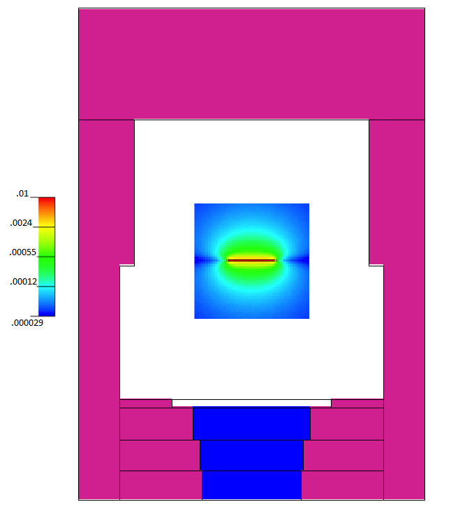
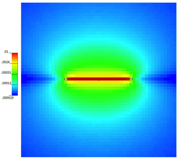
The MCNP6 modeling used for the design is comprised of spent fuel samples from the LWR-PROTEUS Phase II program and a hot cell of the HOTLAB that can accommodate the 40-cm long sample. For the considered sample, UOX with ~70MWd/kg burnup and more than 10 years cooling time, the neutron source is modeled solely as Cm-244 spontaneous fission reactions as it represents more than 99% of the emitted neutrons. Figure 1 illustrates the distribution of the total flux in the hot cell. Table I quantifies how the total and fast flux (threshold at 0.8 MeV) decreases as the distance between the source and the tallied volume increases. The contribution of neutrons scattered in the hot cell and in the fuel sample gets larger as distance increases (total-flux-to-uncollided-flux ratio). This increase is stronger for the total flux than for the fast flux, since the neutrons that undergo scattering have lower energies, contributing mostly to the lower energy bins. The relative intensity of the fast flux-to-uncollided-flux ratio is constant up to distances of 20 cm. At these distances the scattered neutron contribution is negligible for the detection process. In addition, although the fast flux is reduced by about 85% from 2 to 10 cm and 95% from 2 to 20 cm, the fast neutron flux remains sufficiently high.
| Distance | Total Flux (all E / E > 0.8MeV) |
Uncollided-to-total Flux (all E / E > 0.8MeV) |
Proton Recoil Rate (s-1) |
|---|---|---|---|
| 2 cm | 6.01 / 6.25 | 1.26 / 1.19 | 115 |
| 10 cm | 1.00+ / 1.00+ | 1.30 / 1.18 | 16.0 |
| 20 cm | 0.39 / 0.37 | 1.39 / 1.19 | 5.85 |
| 50 cm | 0.11 / 0.08 | 2.08 / 1.30 | 1.44 |
| 100 cm | 0.07 / 0.03 | 4.69 / 1.75 | 0.51 |
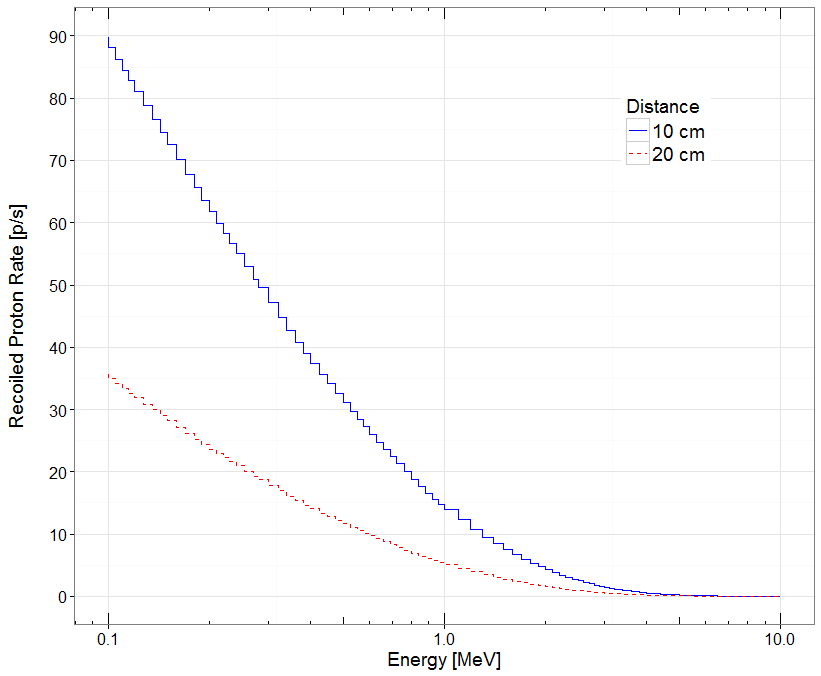
The efficiency of the detector can be initially estimated by the count rate of recoil nuclei (light collection and electronic components are assumed perfect), through which the detection of fast neutrons takes place in organic scintillators. All organic scintillators contain carbon (C) as well as hydrogen (H) atoms. Because of the decreased scintillation efficiency for high linear energy transfer (LET) particles, C recoils do not contribute significantly to the detector output. As a first approximation it is sufficient to account only for the recoil nuclei coming from scattering on H. Since the number of neutrons emitted per second by the spent fuel is known, the neutron flux Φ (in neutrons/cm2/s) at the detector location can be calculated and the rate of elastic scattering with H atoms, which is the rate of recoil protons in the detector, can be calculated with MCNP. An energy threshold typically of the order of 0.1 to 1 MeV is chosen. To apply this threshold, the energy distributions of the recoil protons need to be calculated. A very important simplification holds for H, since the elastic scattering process is isotropic in the center of mass coordinate system. The proton recoil energy distribution, and subsequently the response function of the detector, has a simple rectangle shape extending from zero to the full incident neutron energy. By summing the contributions of the neutrons from each energy group for the different proton recoil energy bins the final form of the proton energy spectrum is produced as shown in Figure 2. The last column in Table I presents the calculated count rate in protons per second assuming an energy threshold of 0.8 MeV and a detector volume of 1 cm3, showing its strong decrease with the distance between the detector and the spent fuel segment. In the distance range of interest (~10 cm to 20 cm) the count rate is still high enough to achieve reasonable measurement times.
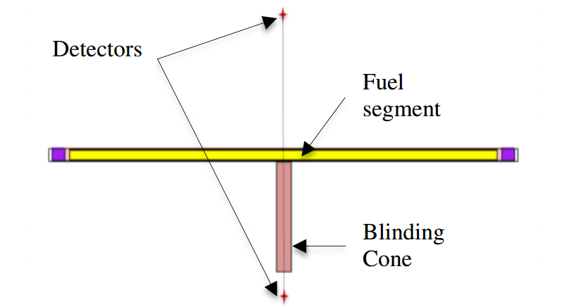
One desirable capability of a new measurement system is to determine the neutron output along the length of the spent fuel rod. A simple method is to use a blinding cone. Two detectors can be placed opposite each other around to the central axis of the fuel rod segment, one with a blinding cone between the detector and the rod (see Figure 3). The blinding cone is shielding one detector from the neutrons emitted by the segment of the rod that it is covering, allowing almost exclusively neutrons from the rest of the rod to reach the detector. On the other side of the rod, the other detector is receiving the neutrons of the full segment. If the blinding cone and the distance of the detector from its surface are optimized, the difference of the response of the two detectors will correspond to the contribution of the fuel rod segment behind the cone. For this study we considered a rectangular cuboid blinding cone with a face of 2 ×1 cm2 and a length of 10 cm. It has an H to C ratio of 2 with a density of 0.95 g/cm3. We also considered the axial and radial distribution of neutrons emitted by the rod to be homogeneous. The MCNP simulations showed that the response of the detector to neutrons only emitted by the central 2-cm long segment of the rod is about 1 proton/second, if the 1 cm3 detector is 12 cm away from the rod. This is the response we would ideally obtain by subtracting the detector response for the full rod with and without the blinding cone or using a perfect collimator. In this ideal case a measurement with enough statistics is possible in a reasonable amount of time by optimizing the detector size and geometry. Typically, we would need a useful signal of about 100 counts/seconds and a measurement time of about 100 s at each axial location to ensure a sufficient precision (uncertainty of 1%). This would require an absolute efficiency increase of about a 100. However, with the simplified blinding cone considered here, the estimation of the count rate that corresponds to the blinded 2-cm long segment, coming from the subtraction of the total count rate without and with the blinding cone, is 2.5 protons/s. The blinding cone efficiently shields the blinded segment by blocking 95% of the neutrons emitted by it but it also shields the detector from neutrons born in the rest of the rod. To reach an accurate answer, we will further optimize the blinding cone shape and material, investigate alternative collimation approaches, and characterize the transfer function of the detection system which can be used to apply deconvolution algorithms to improve accuracy.
As mentioned before spent fuel also emits a large quantity of gamma rays, coming mainly from fission products. This is a major issue for some neutron detectors like organic scintillators that are sensitive to both neutrons and photons. Several methods have been developed to discriminate gamma and neutron detection for a wide range of detectors, a rather popular one being the pulse shape discrimination technique (PSD). The PSD technique is based on the differences in pulse shapes of signals from fast neutron and gamma-ray interactions in some organic scintillators. A problem arises by the fact that the intensity of the photon output is much larger than the neutron output in spent fuel which leads to potentially accumulating spurious counts by coincidence phenomena. The intensity of the photon source was estimated by MCNP simulations in order to understand if the PSD technique could be used for the measurements of the fuel rod with the EJ-299 detector. The simulations revealed that the reaction rate induced from the photon source is about a factor 105 larger than from the neutron source. With such a high rate and a scintillation decay constant for neutrons of the order of 460 ns the dead-time is unreasonably high and the PSD probably will not be sufficient. An advanced design using high-Z material (e.g. lead) to help shielding the detector from gamma-rays might be adequate for improving the fast-neutron-to-gamma-ray ratio and allow using PSD successfully.
The results of the study will be used as guidelines for the choice of the optimal detector configuration for measurement of neutron emitted by spent fuel. An interesting proposition is to sculpt the blinding cone into a more appropriate shape in order to improve the resolution of the system. In addition, the presence of such a strong photon source is calling for further measures to discriminate gamma-ray from neutron signal. PSD should probably be used in combination with photon shielding. To conclude, the ultimate goal of this project is to build a robust measuring unit which will allow the characterization of the fast neutron source for the full fuel rod in less than 6 hours. This will be a major step in the effort of PSI to improve their capabilities to characterize spent fuel rods.


