
Gallery
(If not stated otherwise, the photos are "CREMA collaboration / PSI").

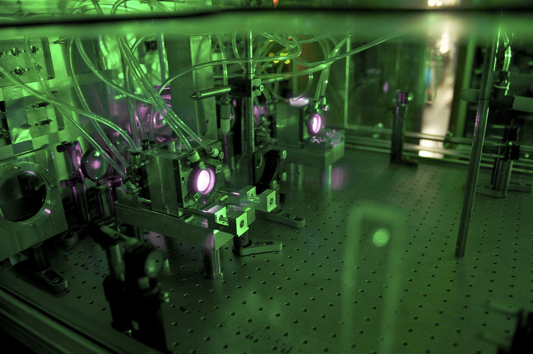
Some impressions of our laser hut. On the right there is the continuous wave (cw) part of our laser system. This is mainly composed by a frequency stabilized and tunable TiSa laser (in green). On the left you see the pulsed oscillator-amplifier system TiSa laser (in green-blue). The Raman cell (horizontal metallic tube) is partially visible left of the pulsed TiSa laser. The vertical metallic tube (left in front) transports the 6 micrometer radiation from the laser hut to the target region avoiding water absorption. The disk laser is placed behind the curtains on the back.
Two water cooled disk laser heads pumped with 1000W (@940 nm) from a fiber coupled diode laser. Each laser head contains an Yb:YAG thin disk (active medium) surrounded by a multipass optical system for the pump radiation.(Photo: PSI/ A. Antognini, F. Reiser)
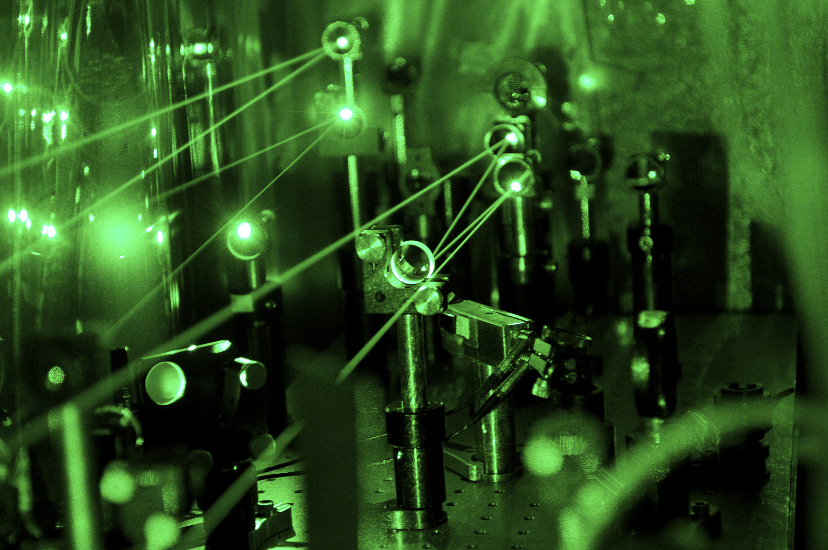
Another view of the frequency douling stages.(Photo: PSI/ A. Antognini, F. Reiser)
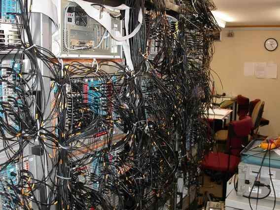
The electronics used to read out the x-ray and muon detectors is filling up our control room which is 40 m away from the beam zone.
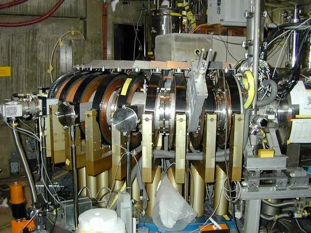
The muon extraction channel (MEC) transports the muon beam from the cyclotron trap (in the back behind the concrete block) to the target (front right). The curvature is needed to clean the muon beam from the huge amount of electrons that leave the cyclotron trap as well.

Target chamber opened: the target is filled with 1 mbar hydrogen gas. Muons enter the target from the lower left side after they have crossed the 5 shiny rings of our
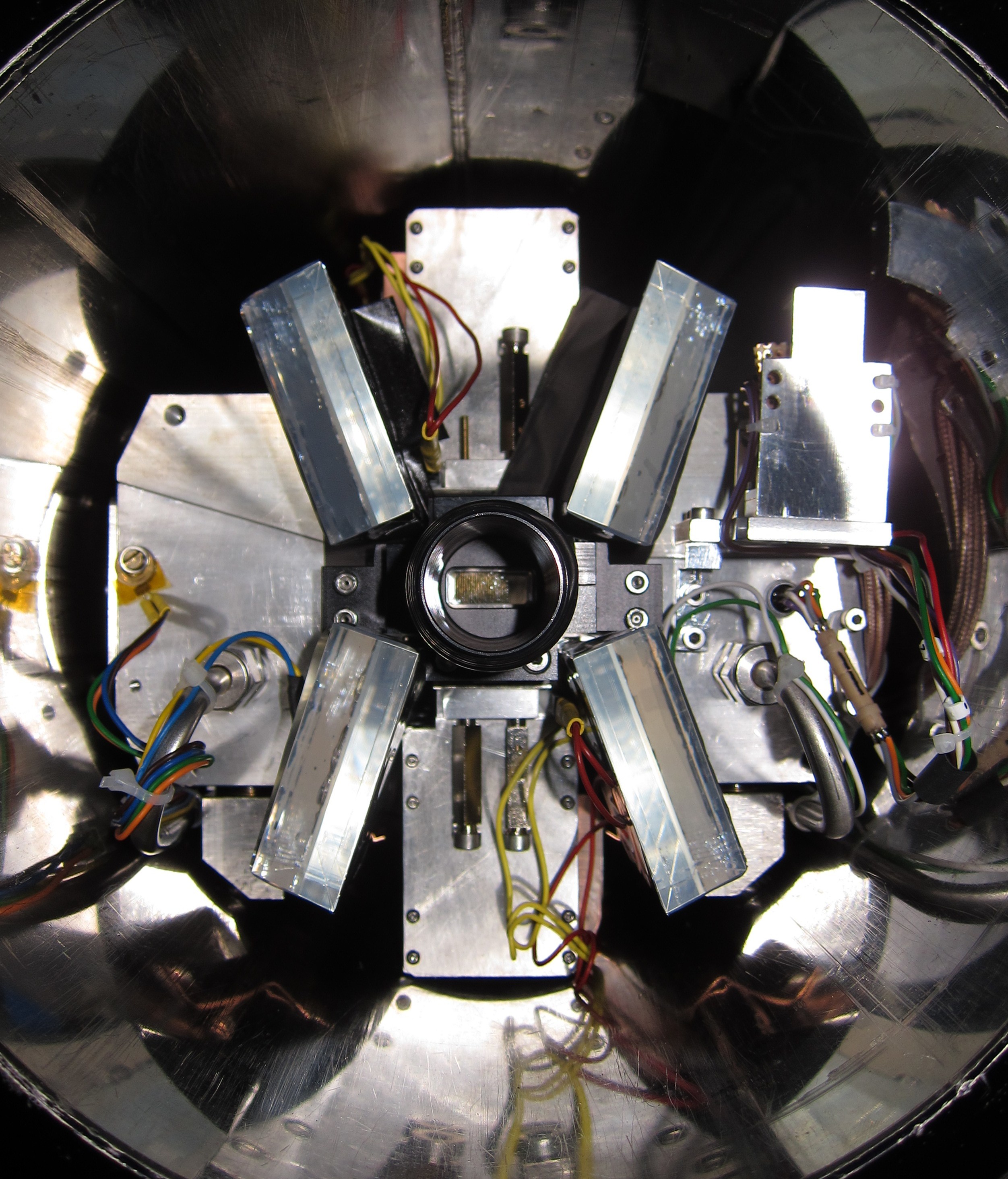
Picture of the gas target with the LAAPDs and scintillator detectors surrounding it. The target is sitting inside the bore hole of a 5T superconducting magnet.

Airial view of the accelerator hall at PSI. Our experiment is in the lower left corner - you see the curved magnetic extraction channel
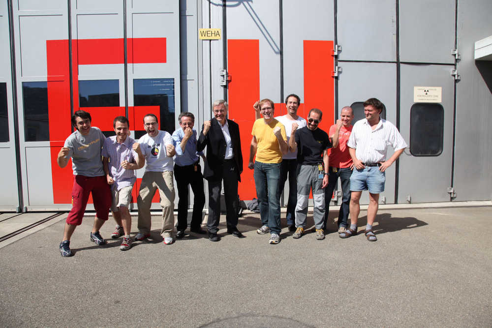
Partial group picture taken in front of the PSI experimental hall.
